Coil Academy / Coil Basics
Standard Steam and Steam Distributing Coils, Explained
Follow the steam, understand the condensate, and see what changes inside each coil.
Two coils can look almost identical from the outside and handle steam differently inside. The difference is how steam reaches the heating surface—and how the water it becomes finds its way out.
In this article13 sections
01 / From steam to warm air
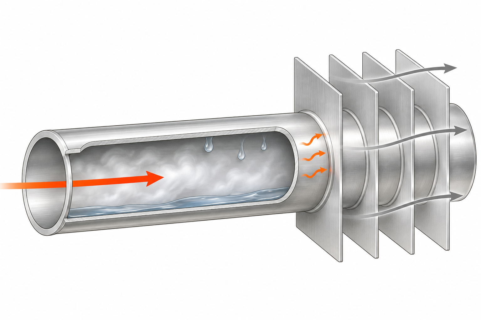
A boiler supplies steam to the coil. As that steam touches the cooler inside surface of a tube, some of it changes back into liquid water. That change of state releases latent heat. The water produced is called condensate.
Heat passes through the tube wall and into the attached fins. Air moving over those external surfaces picks up heat. The air and steam stay on opposite sides of the tube wall; the coil does not intentionally release steam into the air stream.
A useful way to follow the process is: steam arrives, heat crosses the metal, and condensate leaves. Water leaving the coil is an expected result of heating—not evidence, by itself, that something has gone wrong.
02 / The parts you are looking at
The complete assembly
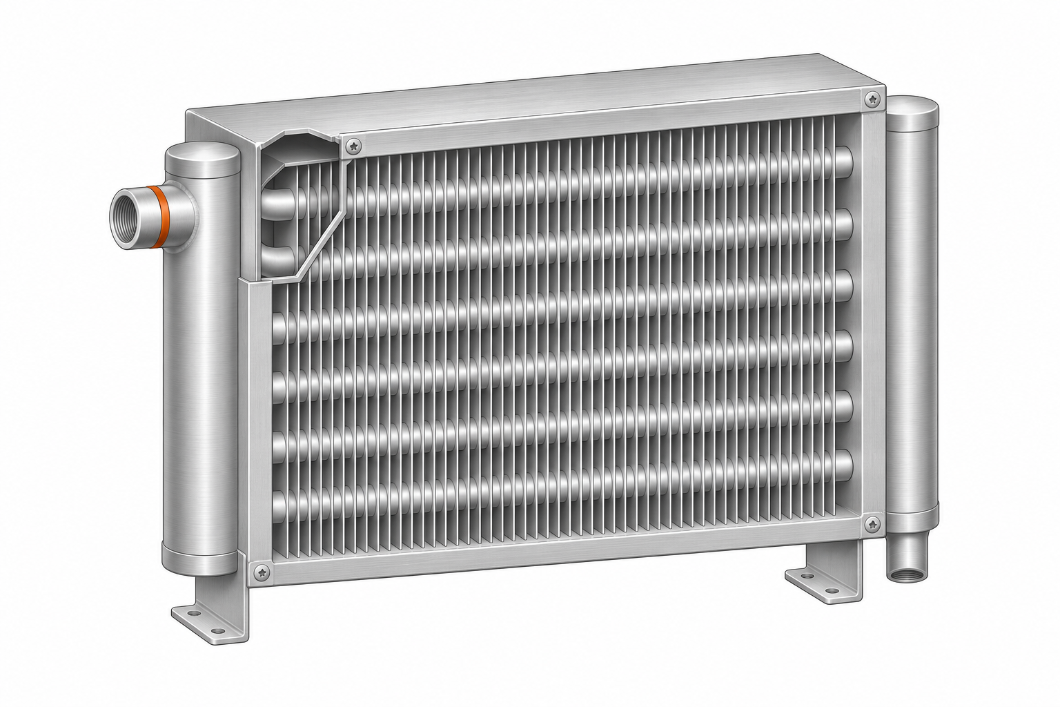
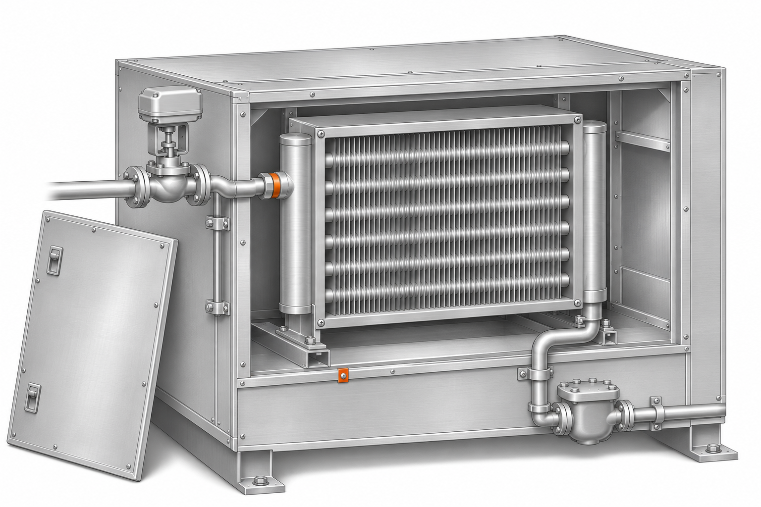
Start with the complete assembly. The casing is the surrounding metal frame that supports the coil and provides its mounting surfaces. Inside it, a bank of thin fins surrounds the heating tubes. The fins provide additional surface for exchanging heat with the air.
The tubes carry steam and condensate. Headers connect groups of tubes to the external piping: the supply side brings steam into the assembly, and the collection side gathers condensate for discharge. Depending on the construction, these connections may be on the same end or on opposite ends.
The distinction between rows and fins is useful here. Rows describe tube positions through the depth of the coil, along the airflow direction. Fin spacing describes how closely the thin fins are packed along the tubes. Neither tells you whether there is a distributing tube hidden inside.
Inside a heating tube
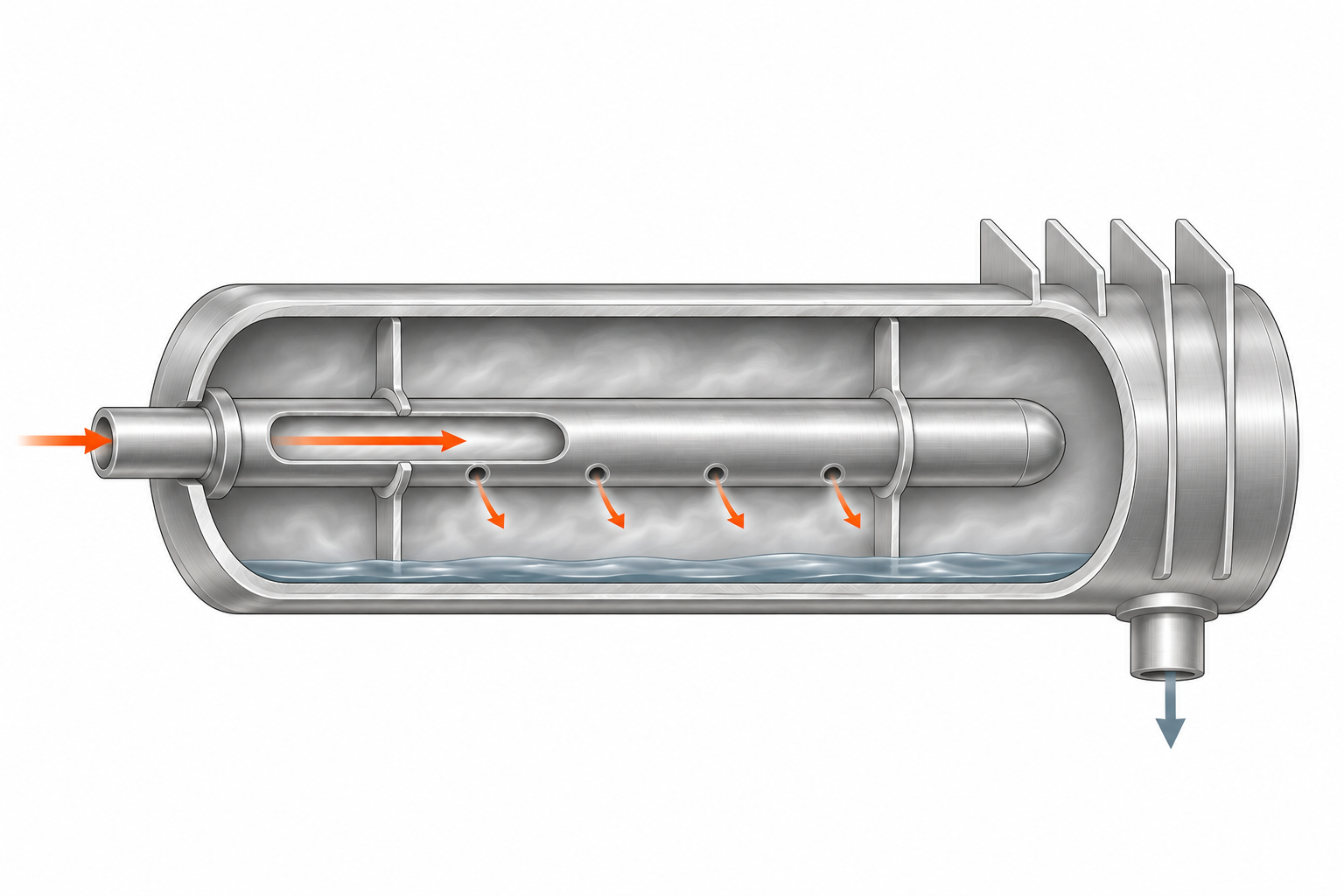
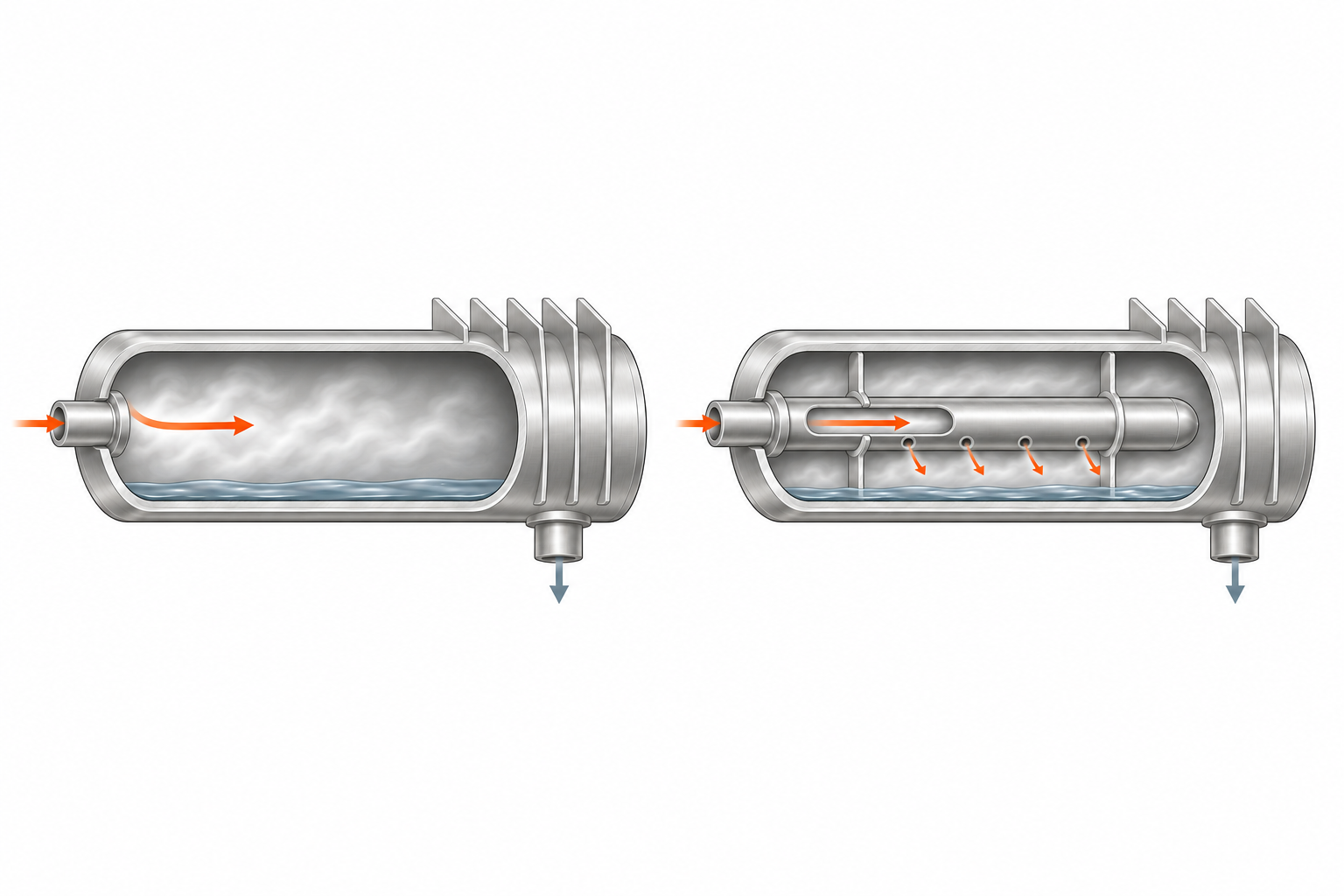
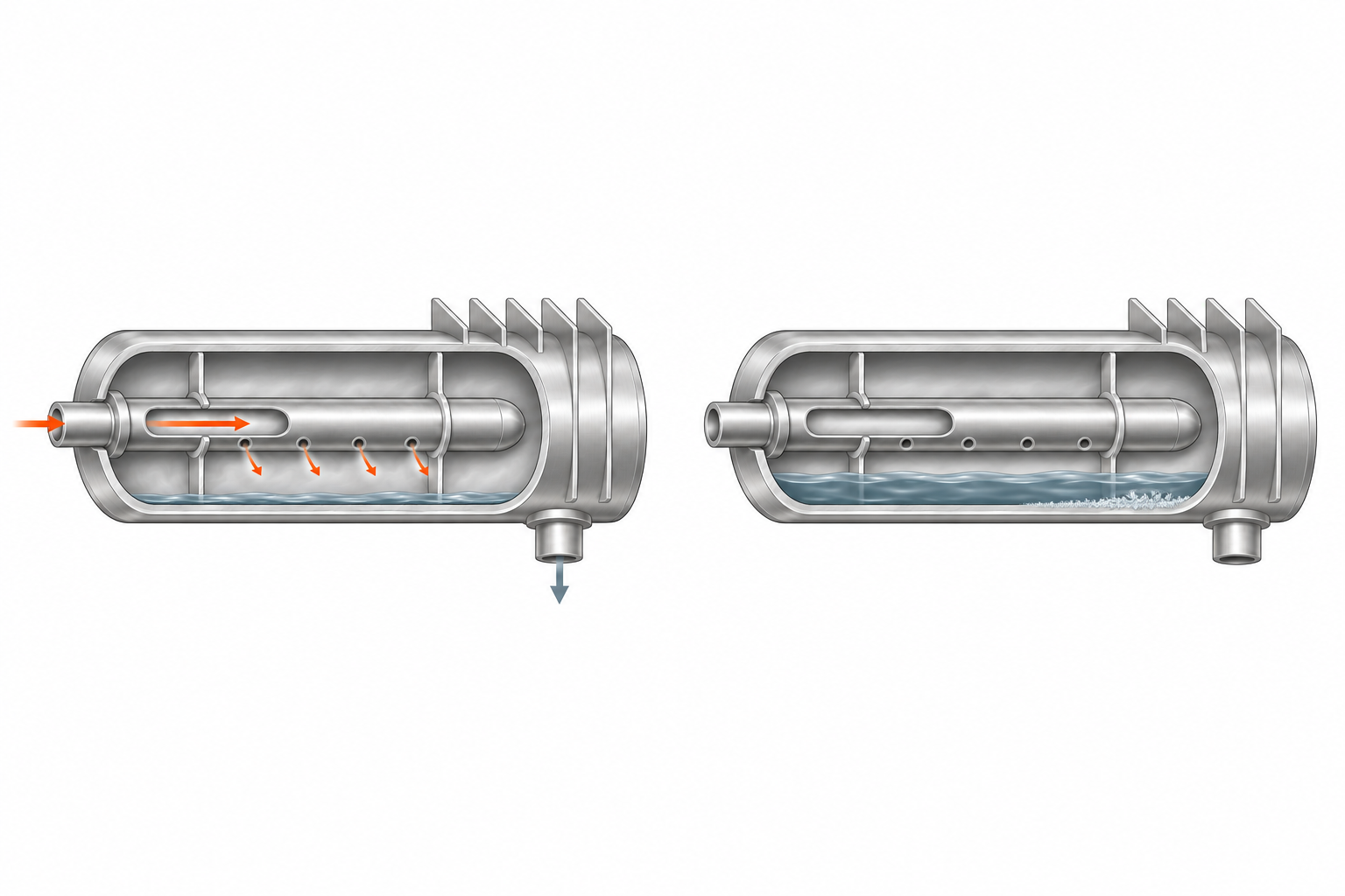
Air passes over the outside of the tubes and fins; steam travels inside the metal. The cutaway below shows a distributing tube inside an outer heating tube. Standard construction has no separate inner tube. The following sections explain each internal path in detail.
03 / Inside a standard steam coil
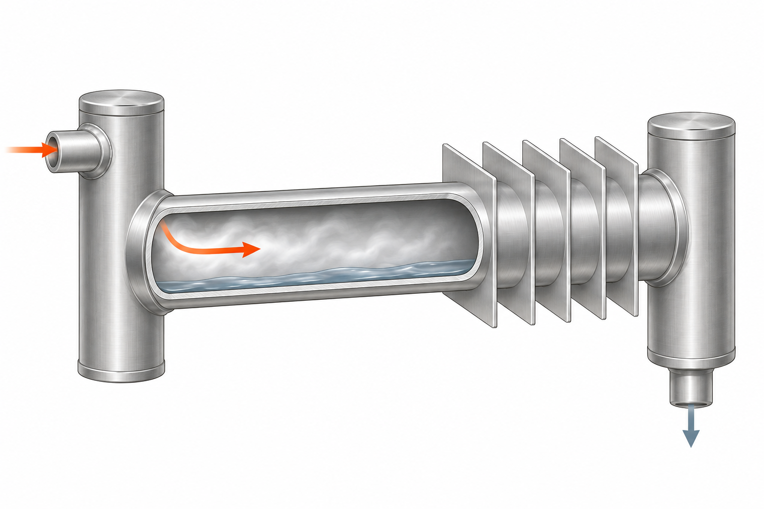
In a standard steam coil, steam enters the heating tubes without a separate inner distribution tube. As it condenses, the resulting water must travel through the coil’s intended drainage path to the outlet. The headers and tube arrangement are designed around that task.
This design is commonly considered for heating or reheat duties where freezing exposure is limited. Airflow, required heat output, steam conditions, construction, and drainage still have to match the application. A water coil with similar dimensions is not automatically a suitable steam replacement.
Connection locations and circuit arrangements vary. Two connections on one side do not prove which construction is inside. Use the original drawing, schedule, model information, or manufacturer confirmation to identify the design.
04 / What the inner tube changes
A steam distributing coil places a smaller tube inside each outer heating tube. Steam travels along that inner tube and leaves through openings distributed along its length. It then enters the space between the two tubes, called the annular space.
The outer tube transfers heat to its fins while condensate forms and drains toward the collection header. Supplying steam at several points helps distribute heat along the tube, rather than relying only on steam entering at one end.
This construction is often used for outdoor-air preheating and other cold-air duties. It is a different internal arrangement, not simply a standard coil with extra rows or a different fin spacing.
05 / Compare the two constructions
Choose the construction around the conditions the coil will actually face. A coil serving already-warm indoor air has a different exposure from one receiving winter outdoor air. Consider the lowest entering-air temperature, how heat is controlled, and whether condensate can leave throughout the operating range.
Standard steam coils are commonly considered for heating and reheat where freezing exposure is limited. Steam distributing construction is commonly considered for outdoor-air preheat and other cold-air duties. Neither label replaces a selection based on airflow, required capacity, steam conditions, and the installation.
The application matters more than the building’s name. A hospital may have an indoor reheat coil and an outdoor-air preheat coil with very different needs. A school or factory can have the same distinction. Identify what the particular coil does, rather than selecting solely by facility type.
| Consideration | Standard steam | Steam distributing |
|---|---|---|
| Inside the heating tube | No separate inner distributing tube. | A perforated inner tube distributes steam into the surrounding space. |
| Typical context | Heating and reheat where freeze exposure is limited. | Outdoor-air preheat and cold-air service, subject to selection. |
| Condensate removal | Requires a properly designed drainage system. | Also requires a properly designed drainage system. |
| What appearance tells you | External shape alone does not confirm internal construction. | External shape alone does not confirm internal construction. |
06 / Startup, steady heating, and reduced demand
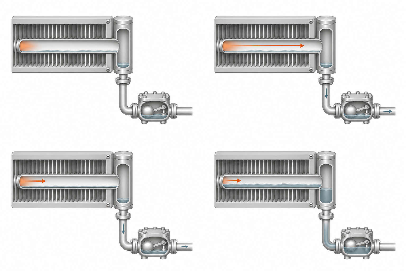
Startup
At startup, the coil and nearby piping may be cooler than they are during normal operation, and air may be present in the steam space. As steam arrives, it warms the metal and produces condensate. Removing air and condensate allows steam to reach the heating surfaces.
Steady heating
During steady heating, steam continues to condense as heat moves into the passing air. This is a continuous exchange, not a one-time filling of the coil. Steam supply, air movement, and condensate discharge work together. The coil’s output depends on the conditions on both sides of the tube wall.
Reduced demand with drainage maintained
When less heat is needed, a modulating control valve can reduce the steam entering the coil. Pressure inside the coil may then fall. That changes more than the heating rate: it can also reduce the pressure available to discharge condensate into the return system.
A coil that heats successfully at full demand can therefore behave differently at part load. Useful operating information includes when a problem appears—during warm-up, mild weather, the coldest conditions, or a change in control position. Those patterns help explain why one full-load observation may miss an intermittent problem.
When drainage stalls
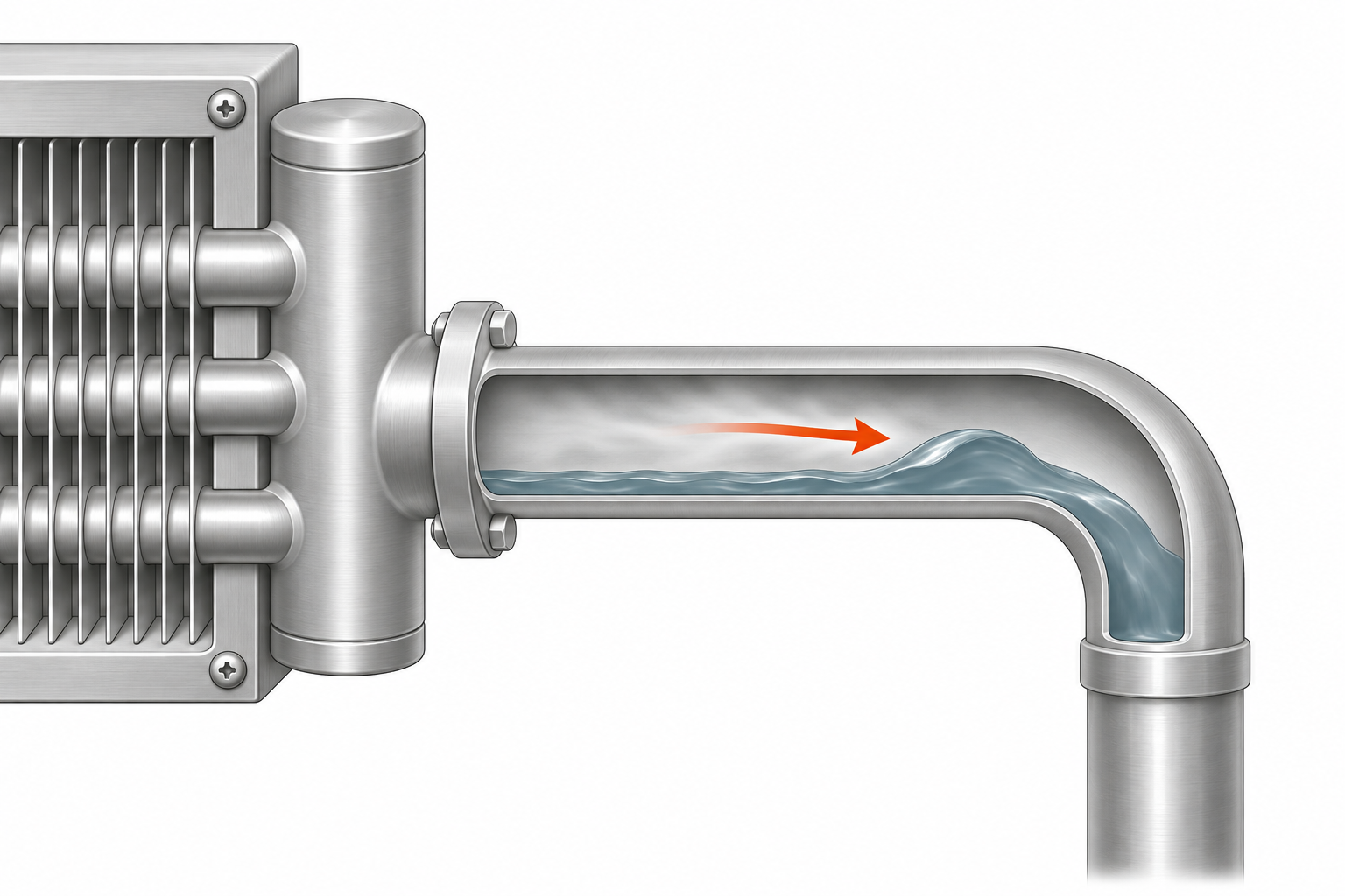
If the pressure available at the coil can no longer overcome return resistance, condensate discharge can slow or stop even with a functioning trap. Retained water can accumulate. This differs from normal reduced demand with drainage maintained.
07 / The equipment around the coil
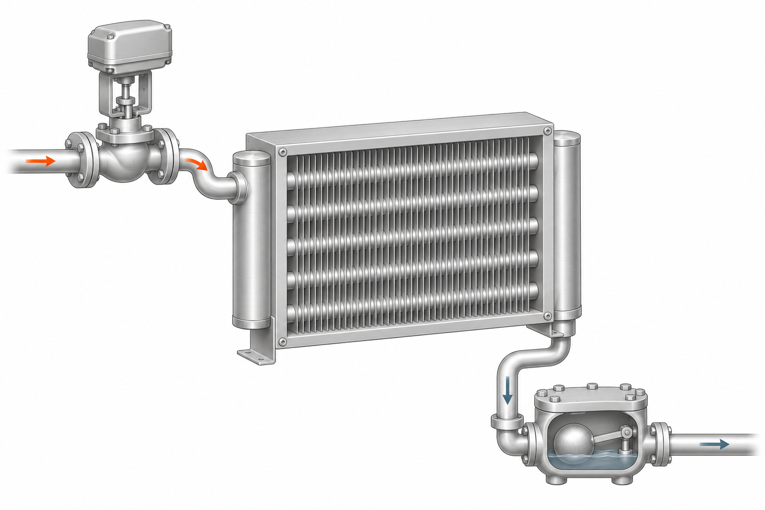
The control valve regulates the supply of steam in response to a heating demand. It belongs to the supply side. The steam trap belongs to the condensate discharge side and performs a different job: removing liquid while limiting the escape of live steam. They are not interchangeable controls.
Air removal matters because air occupying part of the steam space can interfere with steam reaching the heating surface. Depending on the arrangement and trap type, air may be discharged through the trap, through a separate vent, or through both. A vacuum breaker, where specified, admits air when pressure falls below atmospheric pressure; it is not a condensate pump.
Downstream, the condensate return system determines what the coil must drain into. Return pressure and any lift after the trap can increase the resistance to discharge. Gravity can assist when the specified arrangement provides adequate fall and head; it cannot be assumed to solve every return condition.
This is why a steam coil is best understood as part of a system. Its internal construction matters, but so do the supply, controls, air removal, trap, and return. The illustration identifies their relationships without prescribing a universal piping arrangement.
08 / Condensate needs a way out
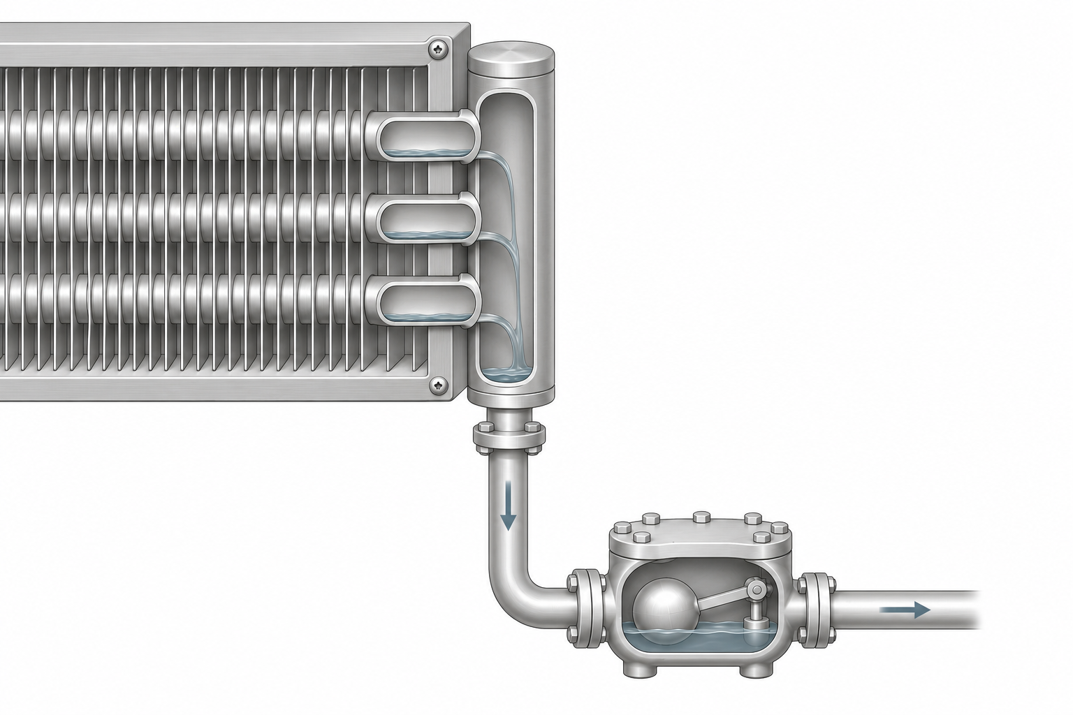
A steam trap automatically discharges condensate while limiting the loss of live steam. Depending on its type, it also removes air and other non-condensable gases. A trap is not a pump: installing one does not guarantee drainage against any return pressure.
Drainage depends on the complete arrangement, including the coil’s specified orientation and pitch, the outlet piping, trap selection, available head, and return conditions. A vacuum breaker or air vent may be part of the specified system; neither should be treated as a universal remedy.
At a lower heating load, a modulating valve can reduce pressure inside the coil. If the available pressure can no longer overcome the return system’s backpressure, condensate removal can slow or stop. This is called stall. A functioning trap can still be unable to drain under those conditions.
Backed-up water can reduce heating performance and expose the system to waterhammer, corrosion, and freezing. Replacing the coil alone may leave the cause in place. The drainage arrangement needs to be reviewed with the operating conditions.
09 / Why “non-freeze” needs context
Steam distributing coils are often sold under the name “non-freeze.” Read that as a description of a freeze-resistant design, not immunity. If condensate remains in the coil and conditions become cold enough, damage is still possible.
The inner tube improves steam distribution while steam is available. It does not supply heat during a steam interruption or remove the need for drainage, controls, and the manufacturer’s cold-weather operating requirements.
10 / What common symptoms can tell you
Symptoms describe what the equipment is doing; they do not identify a single cause on their own. Record the conditions when the symptom appears before deciding that the coil itself is the only problem.
Uneven or inadequate heating
Possible contributors include uneven steam distribution, air in the steam space, accumulated condensate, restricted airflow, fouled surfaces, or conditions that differ from the original duty. Compare air-side and steam-side observations together.
Banging or knocking
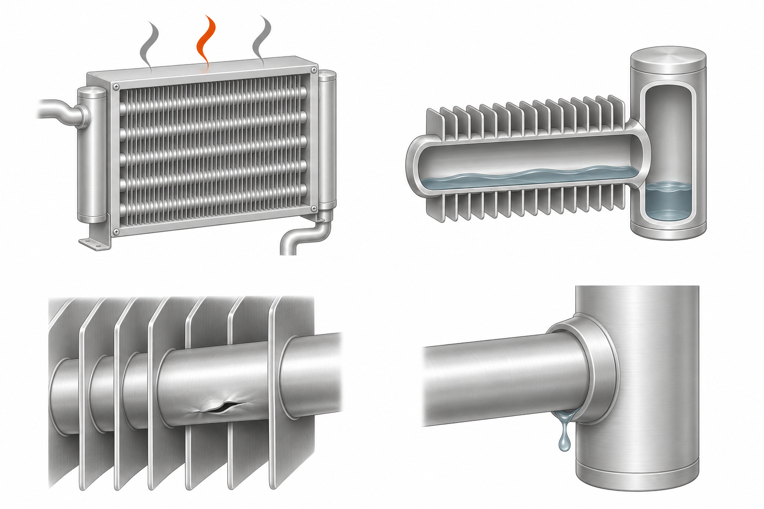
Waterhammer can be associated with condensate being moved by steam or with rapid steam condensation. Noise deserves investigation of the coil and connected piping; it is not a normal indicator of good heating.
Trouble mainly at light load
A relationship with reduced demand can point toward pressure and condensate discharge conditions. A trap check alone may not explain what happens when coil pressure falls.
Repeated freeze damage
Review cold-air exposure, steam availability, controls, and drainage as a group. A distributing construction does not make retained water harmless when heat is unavailable.
Leaks after earlier repairs
Document the leak location and operating history. A failed joint, tube damage, corrosion, and external mechanical stress are different possibilities; the repair history is useful evidence, not a diagnosis.
11 / Four misunderstandings worth clearing up
“Steam distributing means a different fluid.”
Both constructions use steam. The difference is the internal path that delivers it to the heating tube. The inner tube is a distribution component, not a second water circuit.
“More fins always mean a better replacement.”
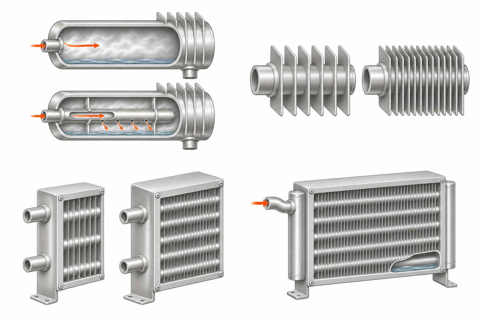
Fin spacing is one part of a selection. It affects air-side performance and must be considered with airflow, available fan pressure, cleaning access, and the intended duty. A denser fin pack is not automatically the right answer.
“Matching the connections is enough.”
Connection fit helps the replacement connect to existing piping, but it does not establish capacity, pressure suitability, internal construction, or drainage orientation. Those are separate characteristics.
“A hot inlet proves the whole coil is working.”
It only proves that the location being observed is hot. It does not establish uniform heating across the face or confirm that condensate is leaving throughout the operating range.
12 / Prepare for a replacement
A replacement needs to fit the equipment and the duty. Gather what you can from the existing submittal, equipment records, and site observations. Mark unknown values as unknown rather than substituting assumptions.
- Identify the construction
- Standard steam or steam distributing; include the original drawing or model information if available.
- Describe the air-side duty
- Air volume, entering air temperature, required leaving temperature or capacity, and exposure to outdoor air.
- Describe the steam system
- Steam conditions available at the coil, design pressure and temperature, control method, and condensate return conditions. Distinguish coil pressure from boiler pressure.
- Document the physical fit
- Casing and fin dimensions, rows, tube and fin construction, connection sizes and positions, mounting, and the required installation orientation.
- Include the operating history
- Leaks, uneven heating, freezing, waterhammer, or drainage problems. Photographs of the coil and surrounding piping add useful context.
13 / A replacement example: the dimensions are only the beginning
Consider an outdoor-air preheat coil in an air-handling unit. Its casing dimensions and two visible connections are easy to record. The old coil has also suffered repeated winter damage, and its available records do not identify the internal construction.
A useful replacement description combines three groups of information. First is fit: the casing, fin area, connections, mounting, and available space. Second is duty: airflow, the lowest entering-air temperature, the required heating result, and steam conditions at the coil. Third is context: the drawing if available, the damage history, control behavior, and condensate return conditions.
That description is more informative than “replace this coil with the same size.” It allows the internal arrangement and the heating duty to be considered together. It also keeps a recurring system problem from disappearing behind a dimension list.
When a value is unknown, say so and include the evidence you do have. A readable nameplate, a previous submittal, and clear photographs can help establish which details still need confirmation.
Coil Recall
Review the article’s main ideas, one card at a time.
Card 1 of 7