Coil Academy / Coil Basics
HVAC Coil Basics: Types, Parts, and Terms Explained
Recognize the main coil types, identify their parts and understand the terms used on drawings and performance schedules.
In this article9 sections
01 / What is an HVAC coil?
An HVAC coil is a heat exchanger: a component that transfers heat between two streams. In the finned coils discussed here, air moves across the outside while water, a water/glycol mixture, steam, or refrigerant travels inside the passages. The metal separates the streams while allowing heat to pass through it.
Heat moves from the warmer side toward the cooler side. A heating coil transfers heat into passing air. A cooling coil takes heat out of that air. The coil does not have to create the heat or the cooling effect itself; it works as part of a system that supplies the appropriate fluid and moves the air.
The air side means the surfaces and passages exposed to airflow. The fluid side means the internal passages carrying the working fluid. “Fluid” includes liquids and gases, so steam and refrigerant belong in this discussion too.
A fan moves air and a pump or refrigeration system moves the working fluid. Those devices are separate from the coil, even when the equipment packages them together. An air-handling unit, or AHU, is an equipment assembly that can contain coils, fans, filters, dampers, and other components.
02 / What the different coil types do
Some coil names describe the working fluid. Others describe a heating or cooling role, a position in the system, or a construction method. The most useful starting point is the job the coil performs.
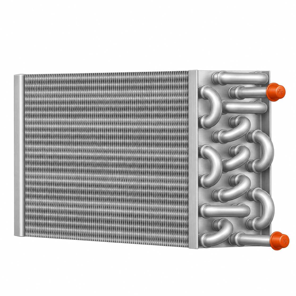
Hot water coils
A hot water coil uses warm or hot circulating water to heat passing air. The water gives up some of its heat and returns to the system at a lower temperature. The water normally stays liquid inside the coil.
Hydronic describes a system that uses a circulating liquid for heat transfer. A hydronic coil may use water or a specified water/glycol mixture. The exact fluid and mixture affect its selection.
Chilled water coils
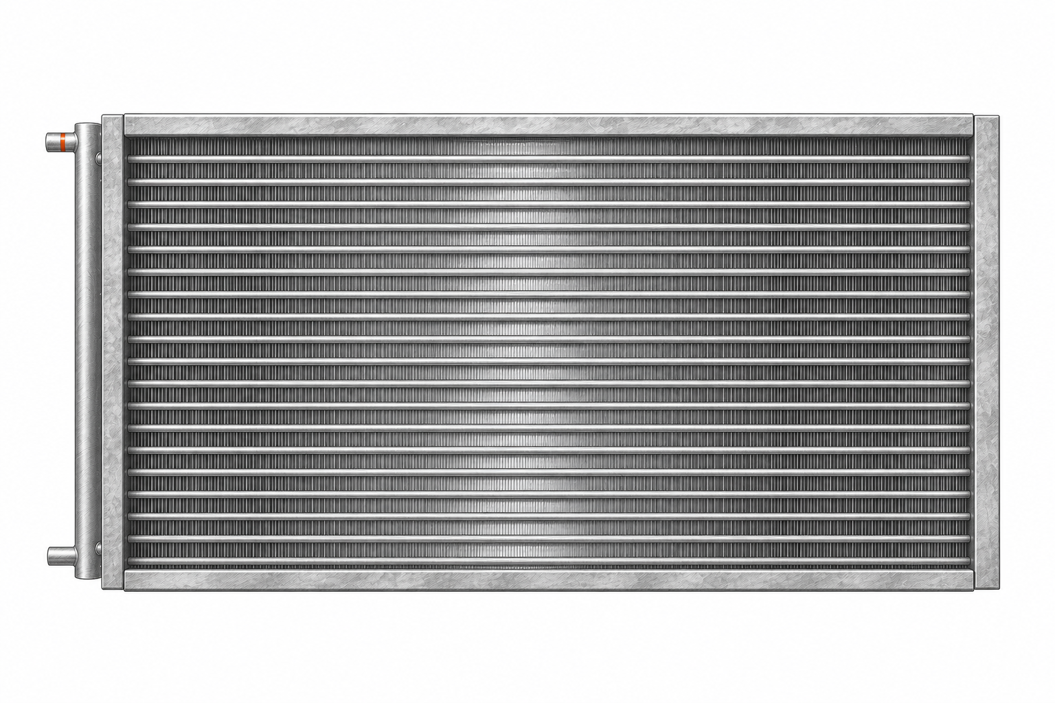
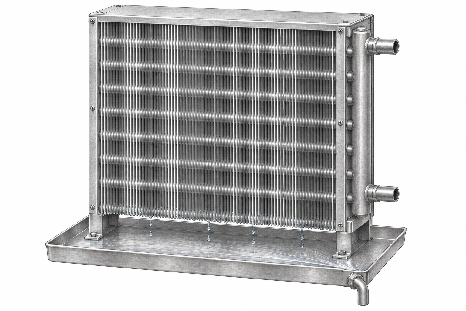
A chilled water coil uses cool circulating water to absorb heat from air. The water leaves warmer than it entered. If the outside surface is below the passing air’s dew point, moisture can also condense on the fins and tubes and drain into a pan.
The water inside the tubes and the water collected in the drain pan have different origins. The first belongs to the circulating system; the second comes from moisture in the air.
Steam coils
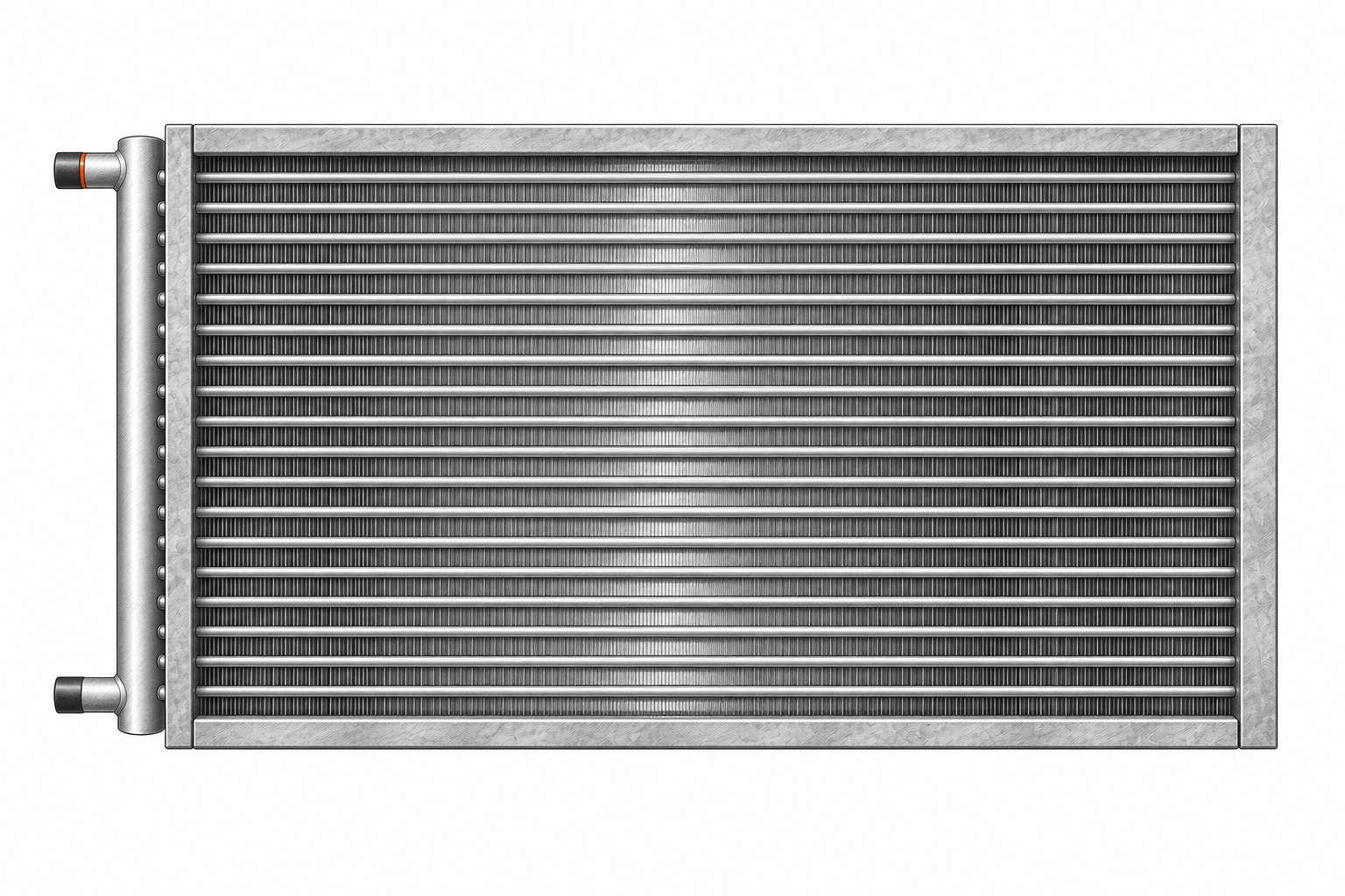
A steam coil heats air as steam condenses into liquid water inside the coil. That liquid is called condensate and needs a suitable discharge path. In standard construction, steam enters the heating passages without a separate inner distributing tube. Steam distributing construction uses an inner tube to deliver steam along the outer heating tube.
Both constructions use steam. Their internal arrangement differs. Water forming inside a steam coil is part of normal heat transfer, rather than moisture removed from the air.
DX evaporator coils
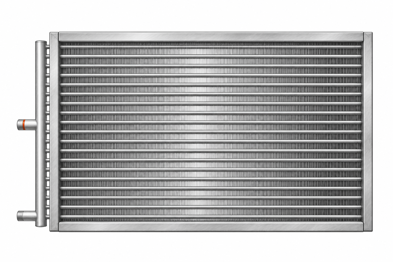
A direct expansion, or DX, evaporator coil cools air using refrigerant that evaporates inside its passages. Evaporation means liquid changing into vapor while absorbing heat. Depending on its surface temperature and the entering air, the coil can also remove moisture from the air.
These coils often have a refrigerant distributor and several small feeder tubes. A chilled water coil and a DX coil can both cool air, but they use different working fluids and internal arrangements.
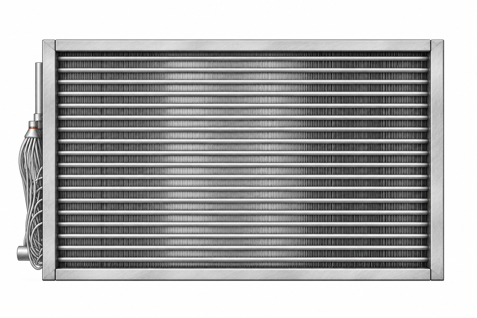
Condenser coils
An air-cooled condenser coil transfers heat from refrigerant to passing air. In conventional condensing operation, the refrigerant gives up heat and changes from vapor into liquid. The air leaves warmer.
In a heat pump, a suitable coil can operate as an evaporator in one mode and a condenser in another. Those names describe its role in the refrigeration cycle, not a permanent indoor-versus-outdoor rule.
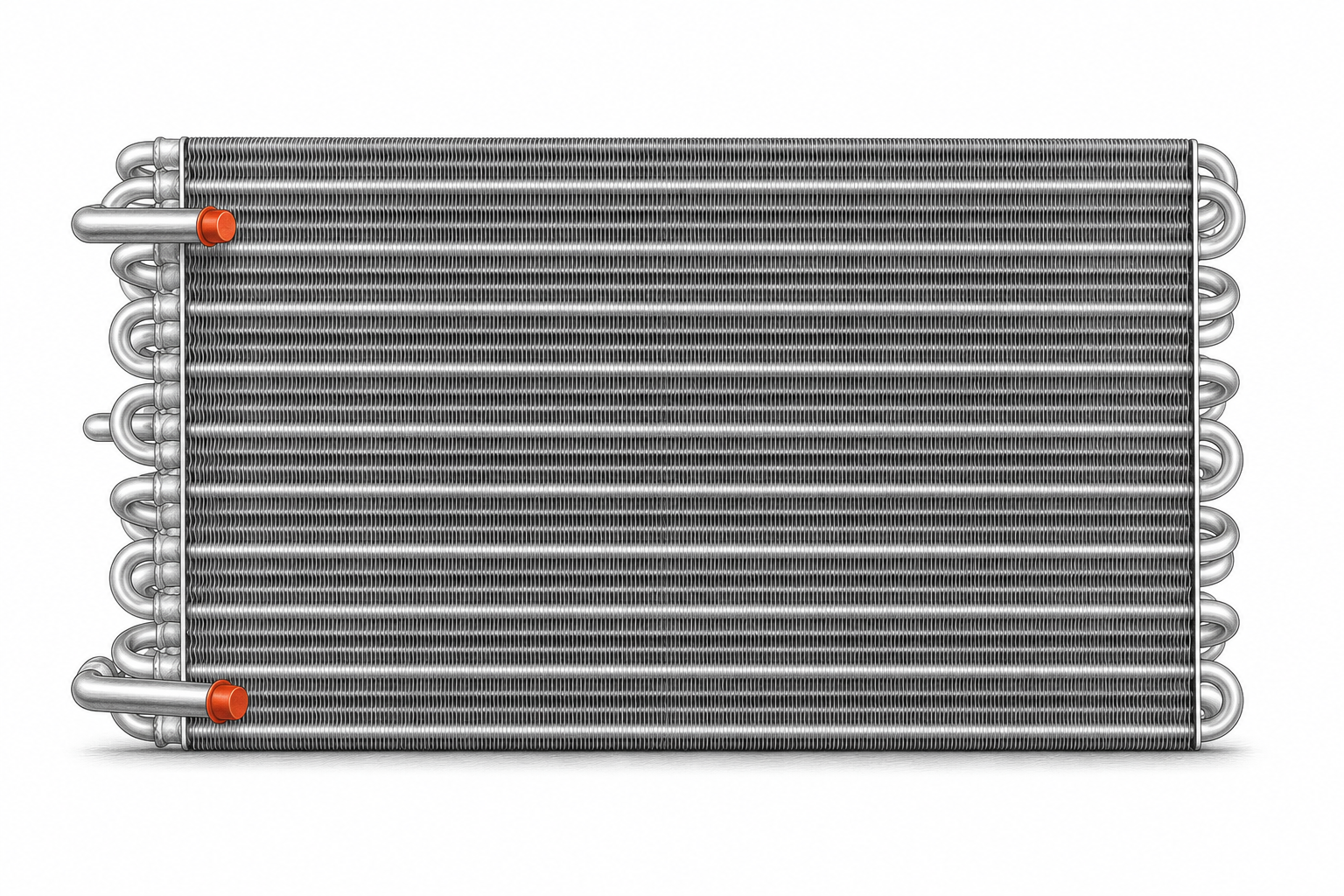
Hot gas reheat coils
A hot gas reheat coil uses heat from the refrigeration system to warm air after a cooling coil has cooled and dehumidified it. Reheat helps deliver air at a suitable temperature without simply undoing the moisture removal.
The reheat coil does not perform the moisture removal itself. Also, reheat describes a job: other arrangements can reheat air with hot water, steam, or electric heat. “Hot gas reheat” specifies the source used in this particular arrangement.
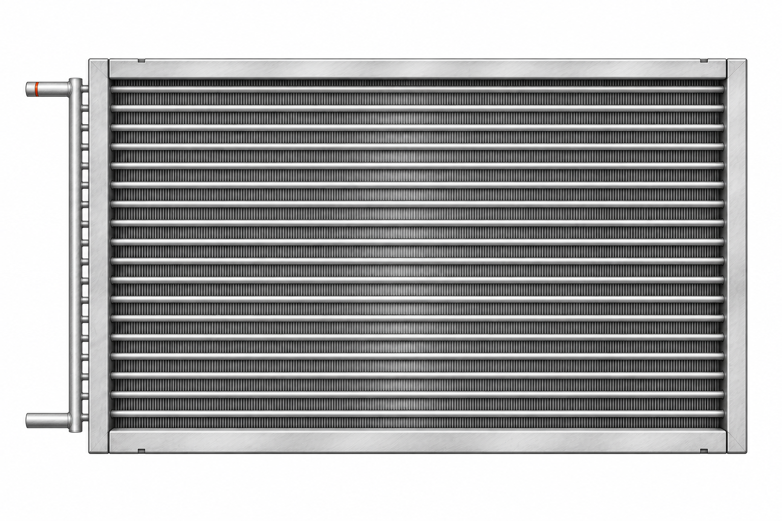
Microchannel coils
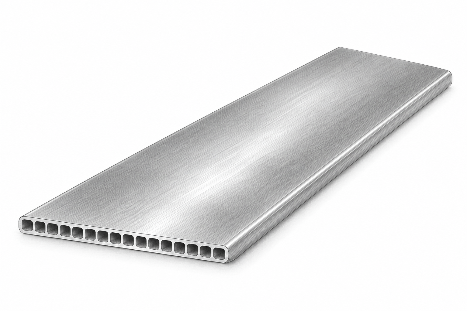
Microchannel names a construction method. Flat tubes contain many small internal passages and join to headers, with fins between the tubes. A microchannel coil can perform a duty such as evaporation or condensation when designed for that service. It is not automatically interchangeable with a round-tube coil.
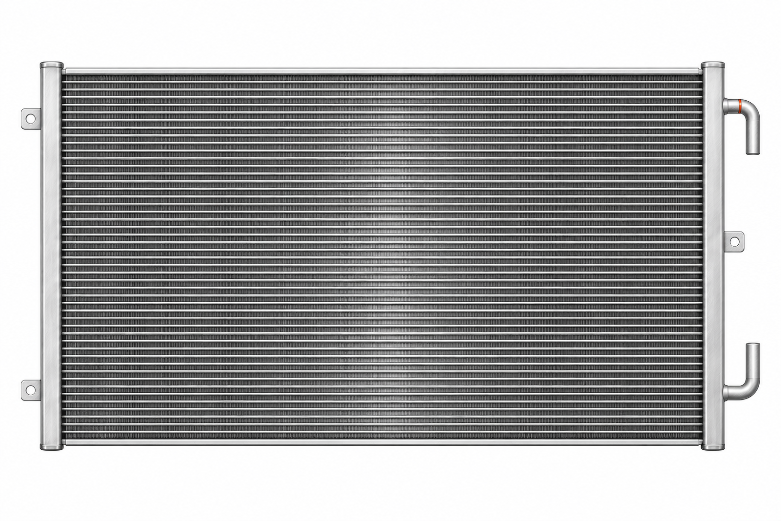
Other names you may encounter
A booster or duct-mounted coil often adds heating within a duct or smaller air distribution assembly. A run-around heat recovery system circulates liquid between coils in separate air streams to transfer heat without mixing those air streams. A refrigeration evaporator applies the same evaporation principle to duties such as cold rooms, with construction chosen for that service.
03 / The parts you are looking at
Casing and mounting flanges
The casing is the surrounding metal frame. It supports the coil assembly and provides surfaces for installation. A flange is an edge formed or added for mounting or joining. Its direction, width, and hole pattern can affect how the coil fits the equipment.
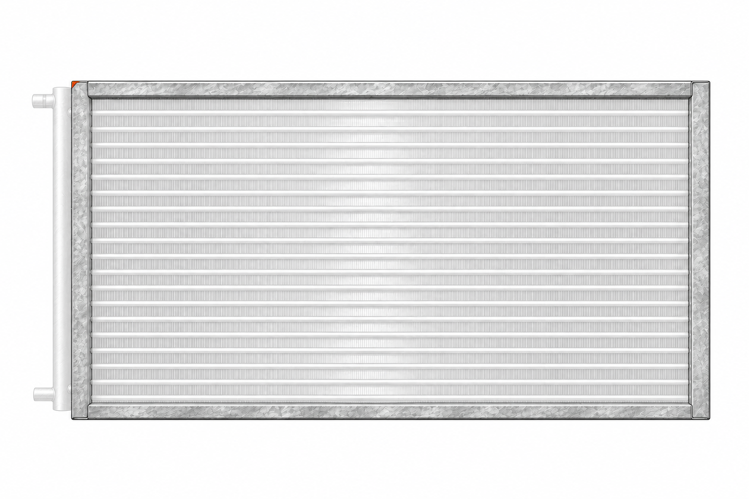
Fin pack, fins, and tubes
The fin pack is the bank of thin metal fins surrounding the tubes. Fins add surface area for heat transfer with the air. Air passes through the spaces between them; the working fluid stays inside the tubes.
Tubes are the passages carrying the working fluid through the coil. In a conventional round-tube coil, the fins are attached around round tubes. A tube sheet or end plate supports the tubes near the ends of the fin pack.
Fin designs
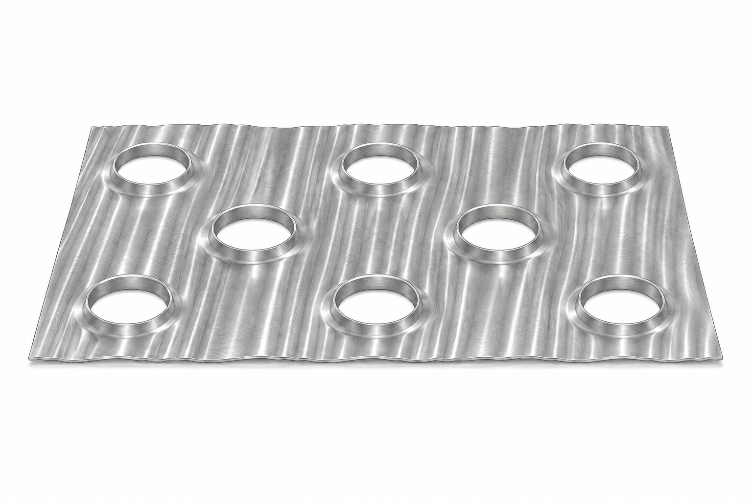
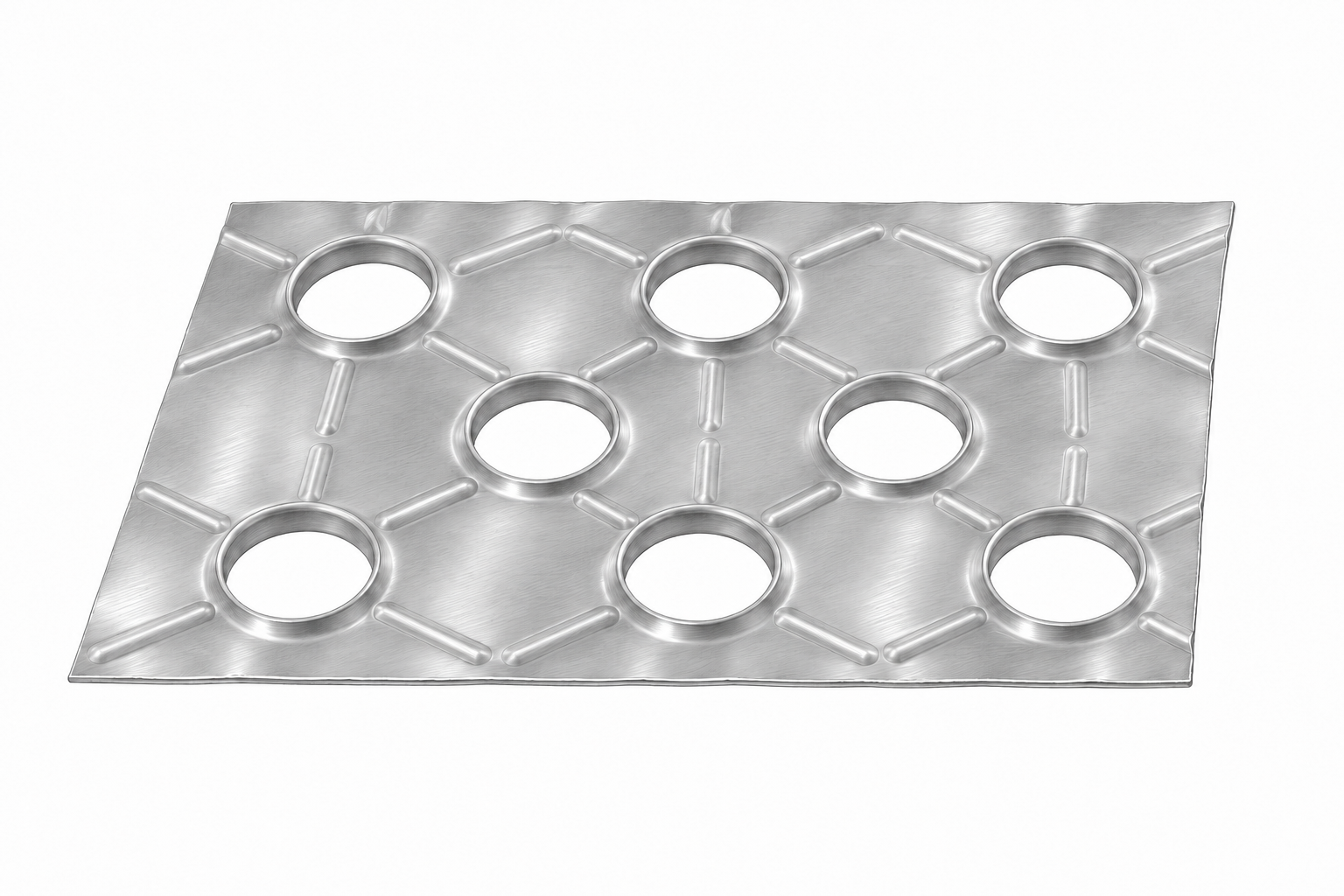
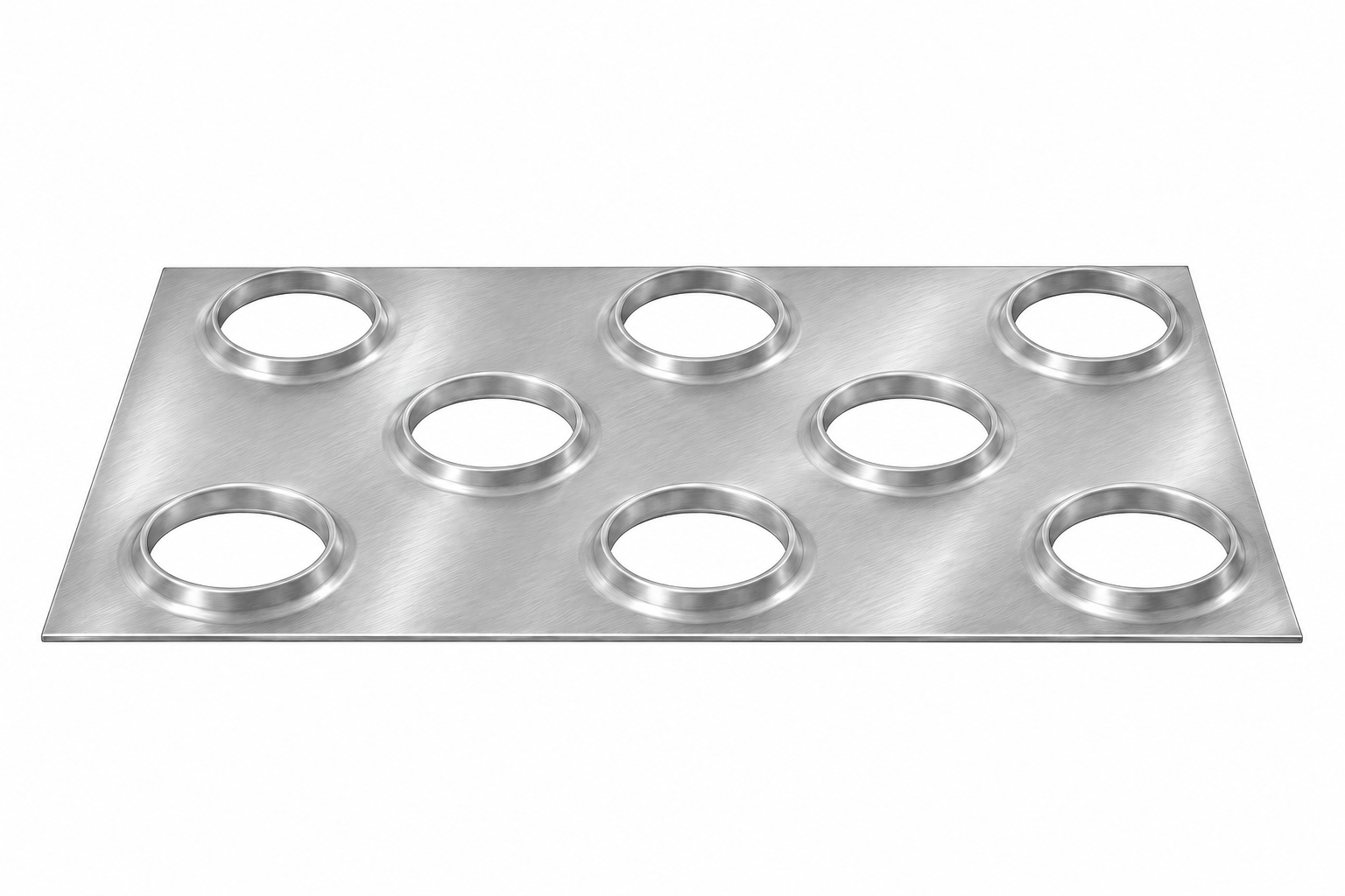
Fin shape is a separate detail from fin spacing. The three examples below use the names Wave, Star and Flat. Fin names and profiles vary among manufacturers; these examples are not a universal list of every available fin surface.
Wave fin
A wave profile forms regular corrugations in the sheet. Those contours change the air-side geometry as air passes through the fin bank.
Star fin
The star pattern uses formed ribs around the tube locations. The raised features distinguish it from a plain flat sheet.
Flat fin
The main sheet remains planar between the drawn collars around the tube openings. Flat describes the surface profile; the sheet still has tube holes and collars.
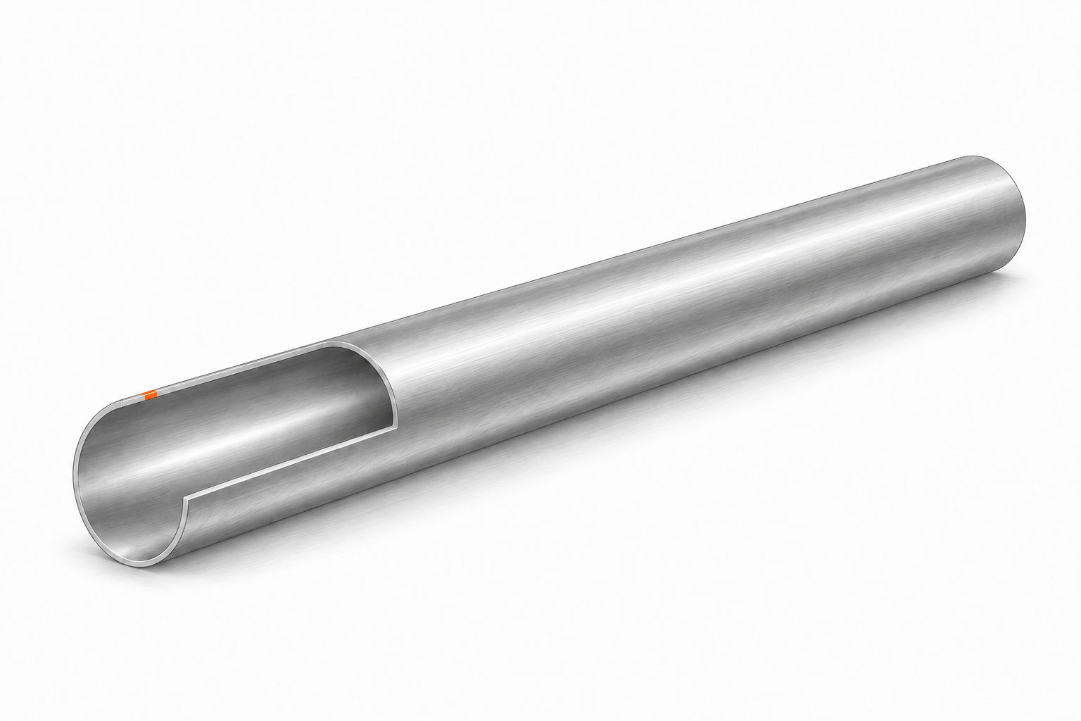
Tube wall and internal passage
A tube has an outside surface, a metal wall and an internal bore. The working fluid travels through that bore. A drawing may specify the tube’s outside diameter and wall thickness separately; either can change the available internal flow area.
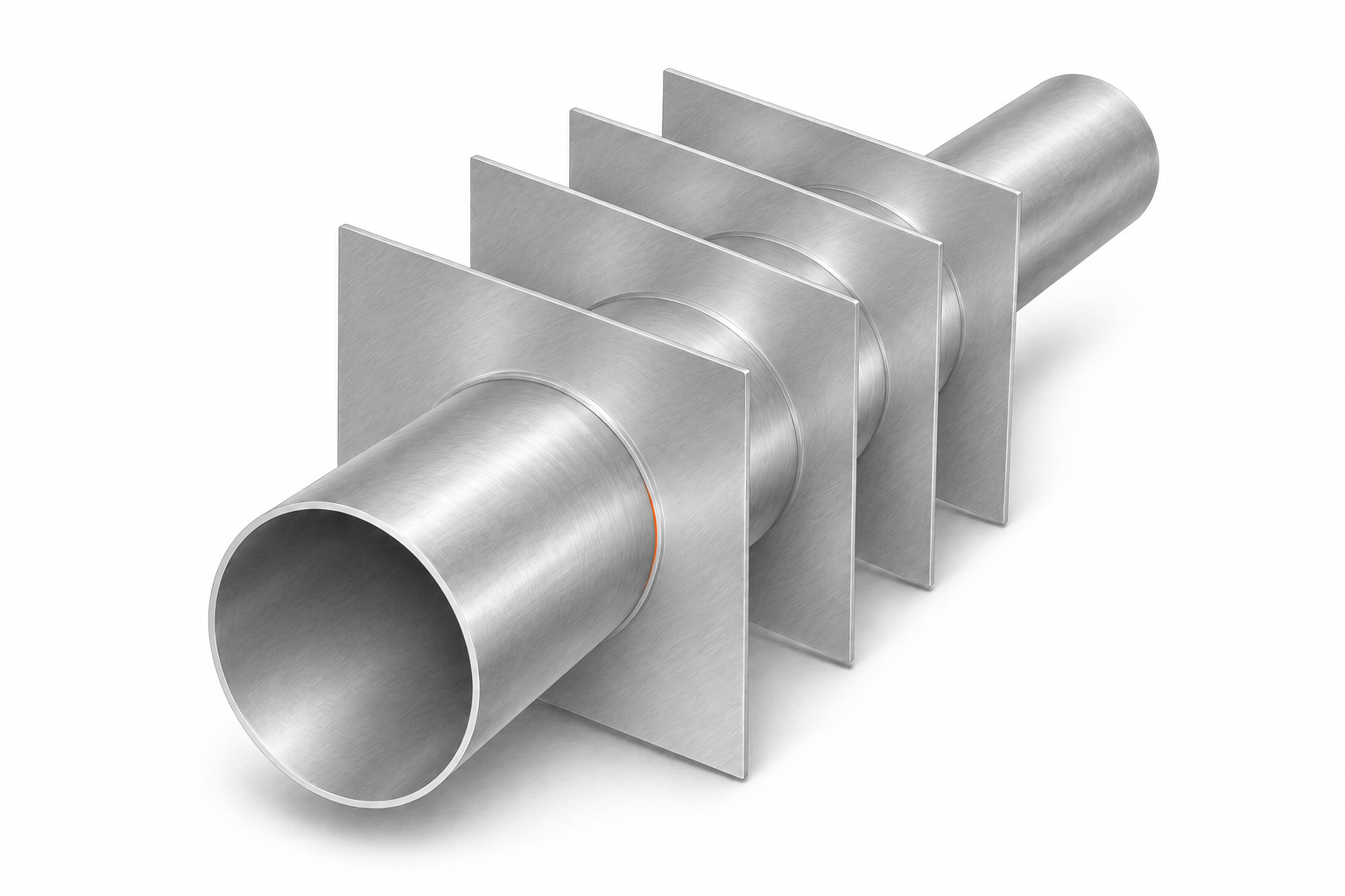
Tube-to-fin contact
Heat has to travel between the tube and the fins. In many conventional coils, the tube is mechanically expanded against the fin collars to create close contact. The collar is formed from the fin around the tube opening; it is not an extra tab projecting from the sheet. Joining methods depend on the construction.
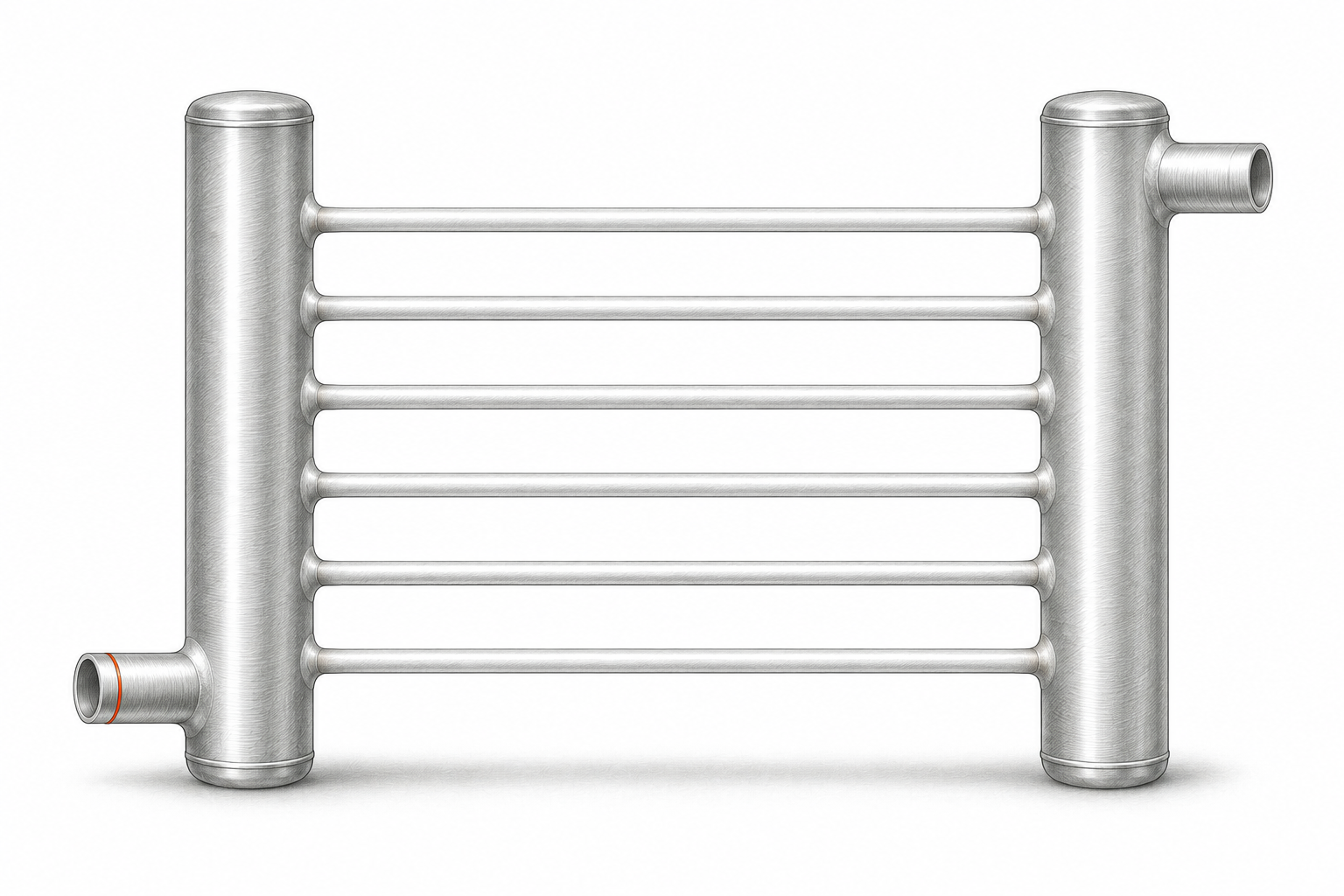
Headers and return bends
A header, also called a manifold in some contexts, connects multiple passages. It can distribute incoming fluid or collect fluid leaving those passages. Its shape and position depend on the construction.
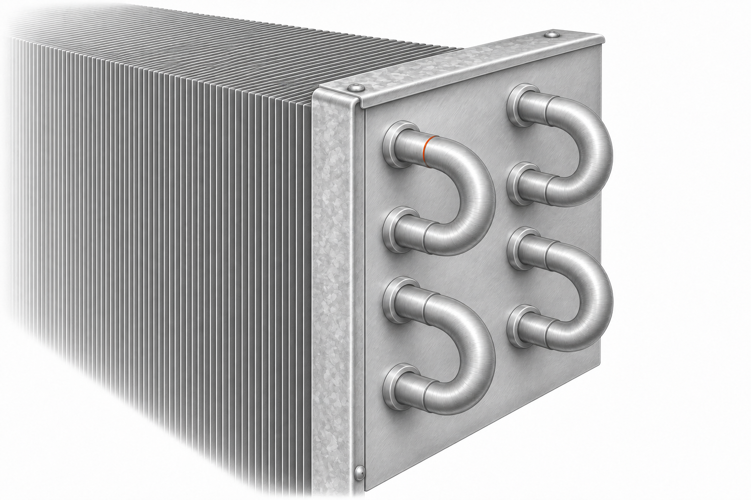
A return bend joins tube sections so fluid can turn and continue through another passage. These bends can project beyond the casing. The outside appearance does not reveal every connection hidden inside a header.
Connections and drain pans
Connections are the external points where the coil joins the system piping. Their size, type, location, and projection all matter. Small vents or drains, when provided, are separate from the main supply and return connections.
A drain pan collects water that forms on the outside of a cooling coil. It belongs to the condensate drainage arrangement and may be part of the surrounding equipment rather than part of the replacement coil itself.
A vent allows trapped air to be released at an appropriate high point. A drain allows liquid to be removed from an appropriate low point. Neither should be confused with the pan drain that collects moisture from outside a cooling coil.
04 / The dimensions that describe a coil
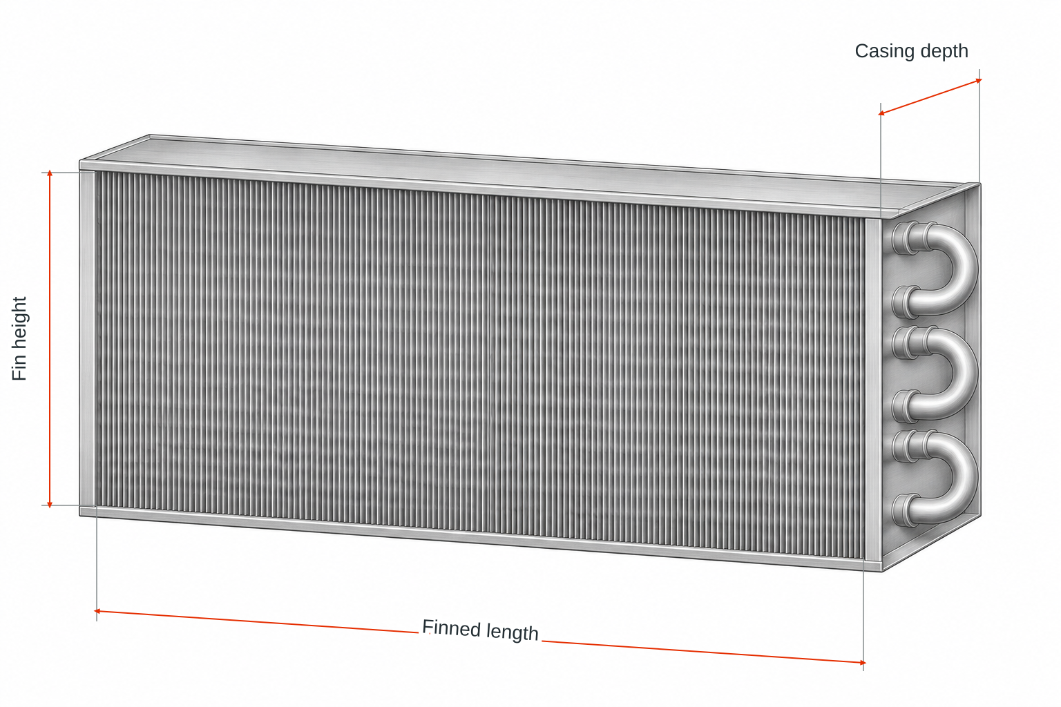
“The coil is this wide” is incomplete unless the endpoints are clear. Separate the finned area, the casing, and the full outer envelope.
Fin height and fin width
Fin height and fin width describe the face of the finned heat-transfer area. Width is often called fin length on drawings. Use the drawing’s defined orientation rather than assuming that different abbreviations mean the same measurement.
The coil face is the broad area presented to the air. Its finned height multiplied by its finned width gives the gross finned face area. That area is different from the total surface area of every fin, and from the smaller open area remaining between metal surfaces.
Casing width, height, and depth
Casing dimensions describe the supporting frame. Depth runs through the coil in the airflow direction. It is different from the width across the face.
Overall dimensions describe an outside envelope, but the inclusion rules must be stated. Headers, bends, mounting features, and connection stubs can extend beyond the casing. Different drawings may include or exclude those projections. A labeled sketch is more useful than an unexplained overall number.
Connection position, projection, and diameter
A centerline runs through the center of a tube or connection. Connection positions are commonly located from a defined casing edge to the connection centerline. State the reference edge and viewing direction.
Projection or stub length is how far a connection extends. Outside diameter, or OD, is measured across its outer surface. Inside diameter, or ID, describes the bore. These measurements are different, and a nominal pipe size is a naming convention that does not necessarily equal measured OD.
05 / Rows, tubes, and fin spacing
Rows through the depth
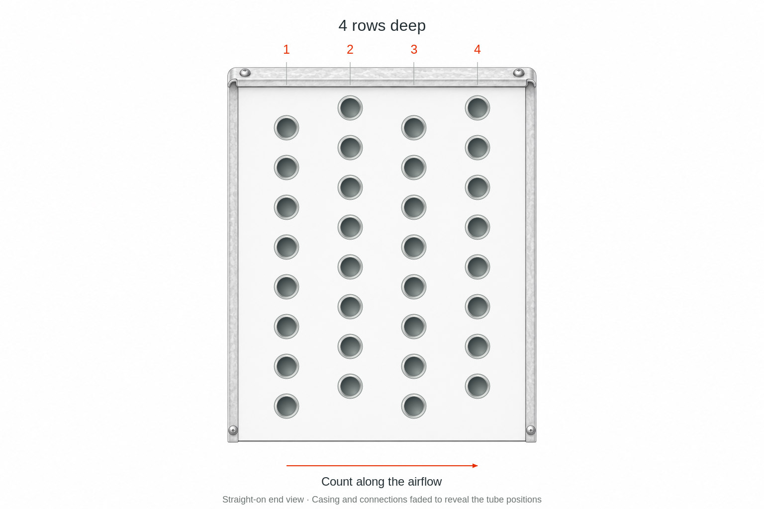
A row describes a tube position through the depth of a conventional fin-and-tube coil, along the airflow direction. It does not mean a horizontal line of fins or the number of tubes stacked from bottom to top.
Increasing rows changes the construction and can change both heat transfer and airflow resistance. A row count alone does not establish capacity or prove that one coil is a suitable replacement for another.
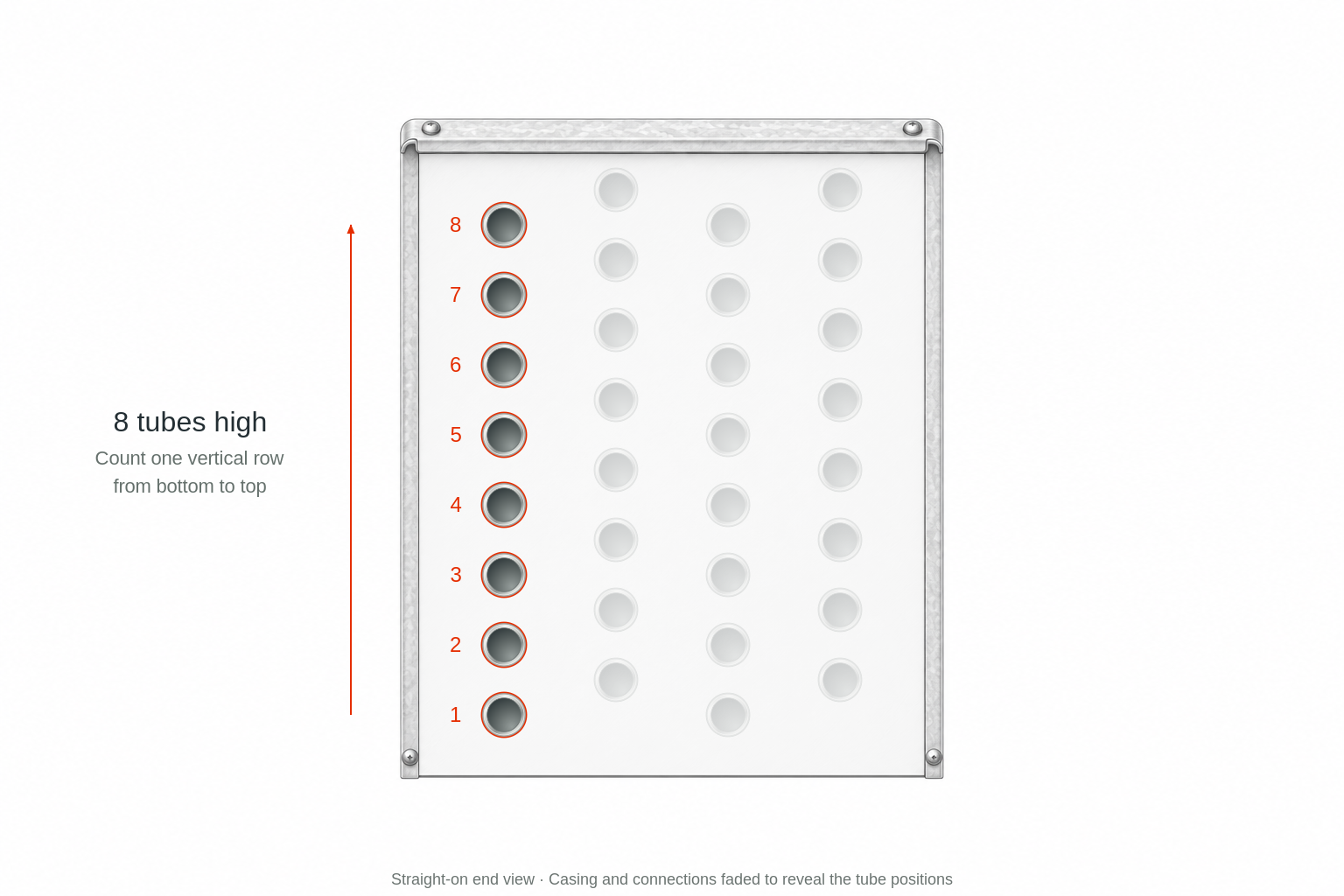
Tubes stacked vertically
The number of tubes stacked vertically describes tube positions from bottom to top in a defined depth row. It is a different count from rows through the depth. Staggered arrangements can offset adjacent depth rows, so a viewing direction matters when counting.
Tube spacing or tube pitch is the center-to-center distance between tube positions. Tube OD describes tube size, while wall thickness describes how much metal separates the internal passage from the outside surface.
Fin spacing and FPI
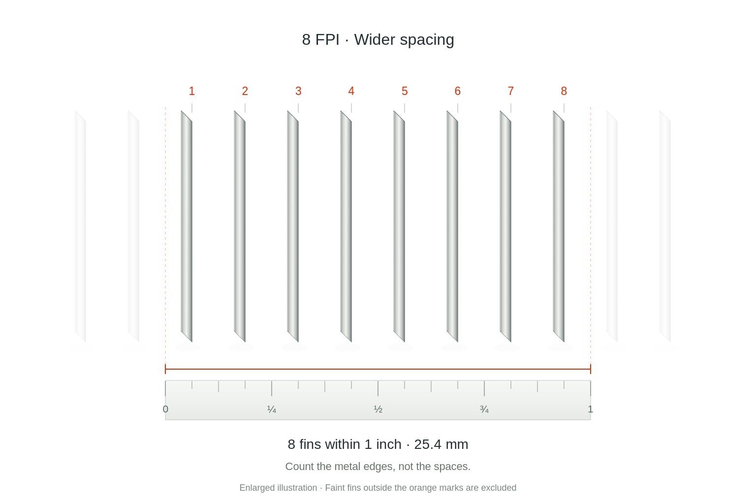
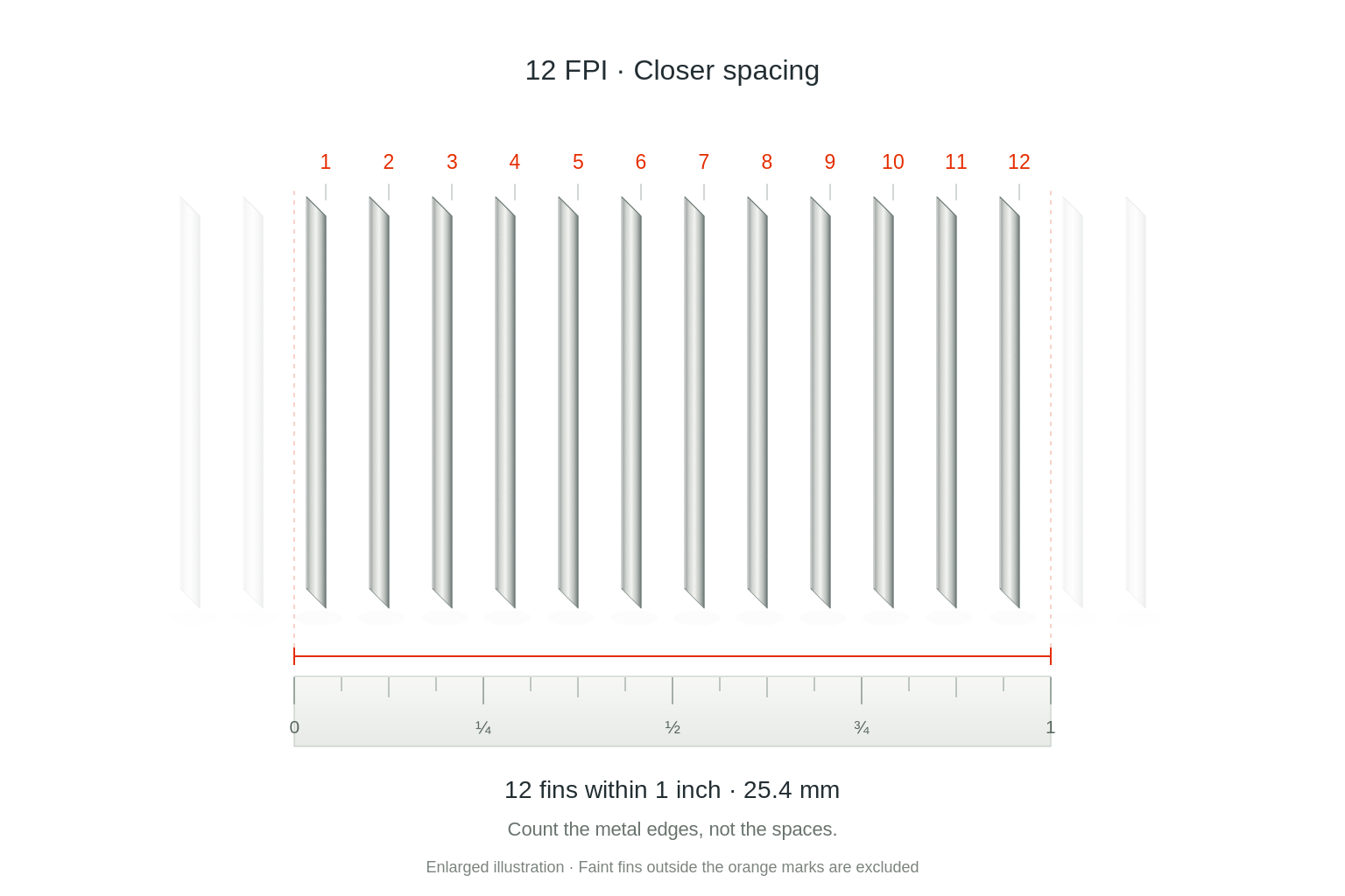
Fins per inch, or FPI, describes the number of fins within one inch along the fin pack. Fin pitch is commonly expressed as a distance between corresponding points on neighboring fins. Higher FPI means more closely spaced fins.
Fin spacing affects surface area, airflow resistance, cleaning access, and behavior where moisture or frost may be present. More fins do not automatically mean a better selection. Fin thickness and fin shape are additional construction details.
8 FPI
12 FPI
06 / How fluid travels through a coil
Circuits and passes
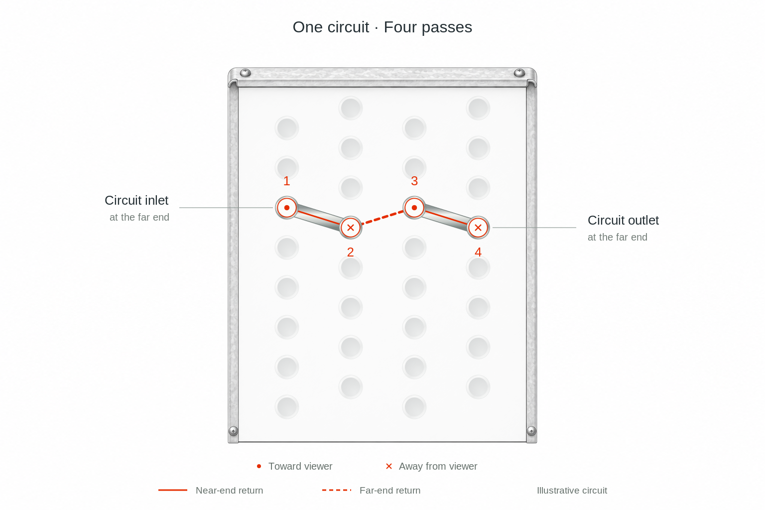
A circuit is an internal flow path through part of a coil. A coil can divide the incoming fluid among multiple paths. A pass is a traversal of a tube or group of passages before the flow turns or is redirected; the exact description should follow the drawing.
Circuiting describes how those passages connect. It affects internal velocity, pressure drop, and heat transfer. Do not infer the circuit count just by counting the two visible external connections or by counting tube rows.
Supply, return, inlet, and outlet
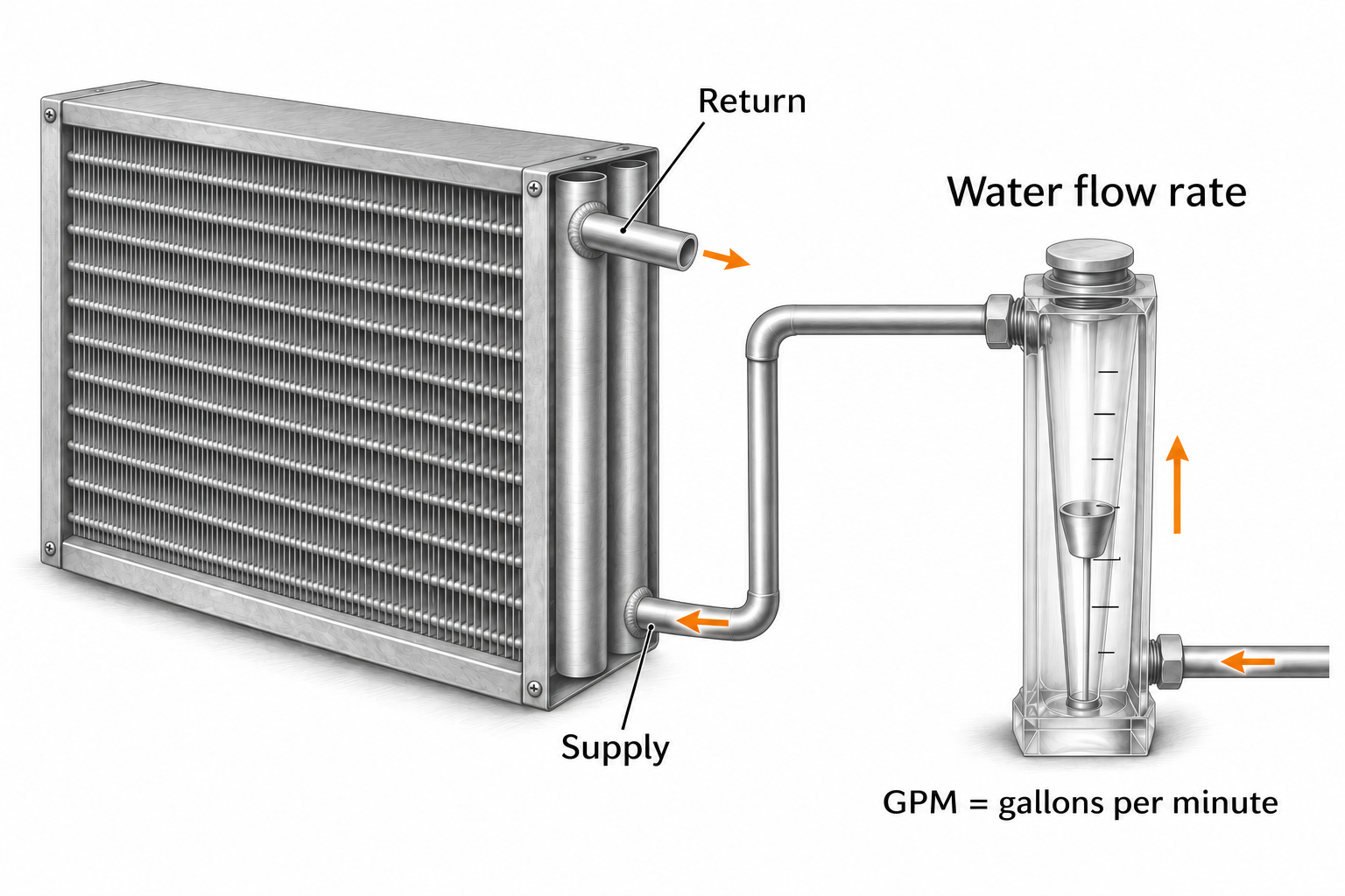
Inlet and outlet state where fluid enters and leaves a component. Supply and return commonly describe the corresponding system connections on water coils. Steam has a steam inlet and a condensate outlet; refrigerant terminology also depends on its role and condition at that point.
A DX distributor divides incoming refrigerant among feeder tubes leading to individual coil circuits. It is different from the inner distributing tube used in a steam distributing coil.
Connection type and connection side
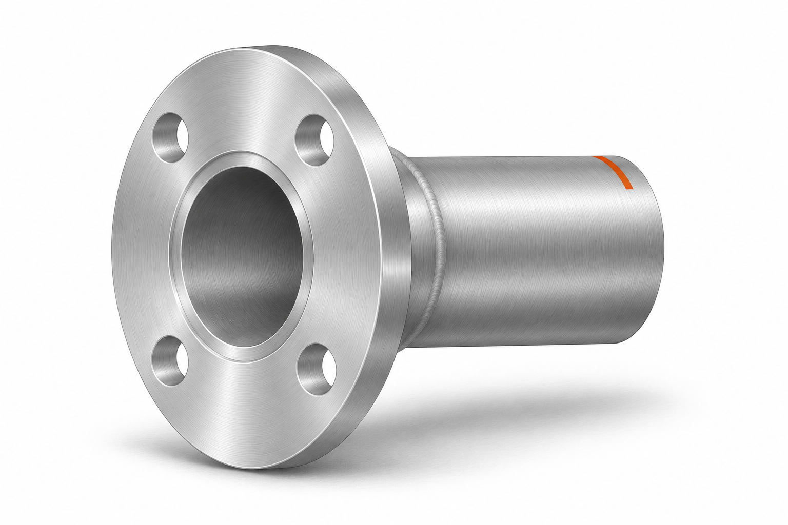
Common connection descriptions include a plain tube or sweat connection, male or female pipe threads, a flange, and a grooved connection. A label such as MPT or FPT describes a threaded connection type; it is not a measurement of the stub’s projection.
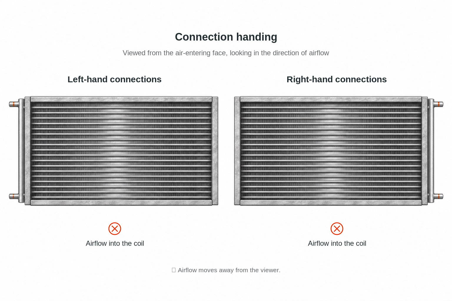
Left-hand and right-hand descriptions only work when everyone uses the same viewing direction. State whether you are looking with or against airflow, and show an airflow arrow in the supporting sketch. Connections may be on the same end or opposite ends.
Sweat connection
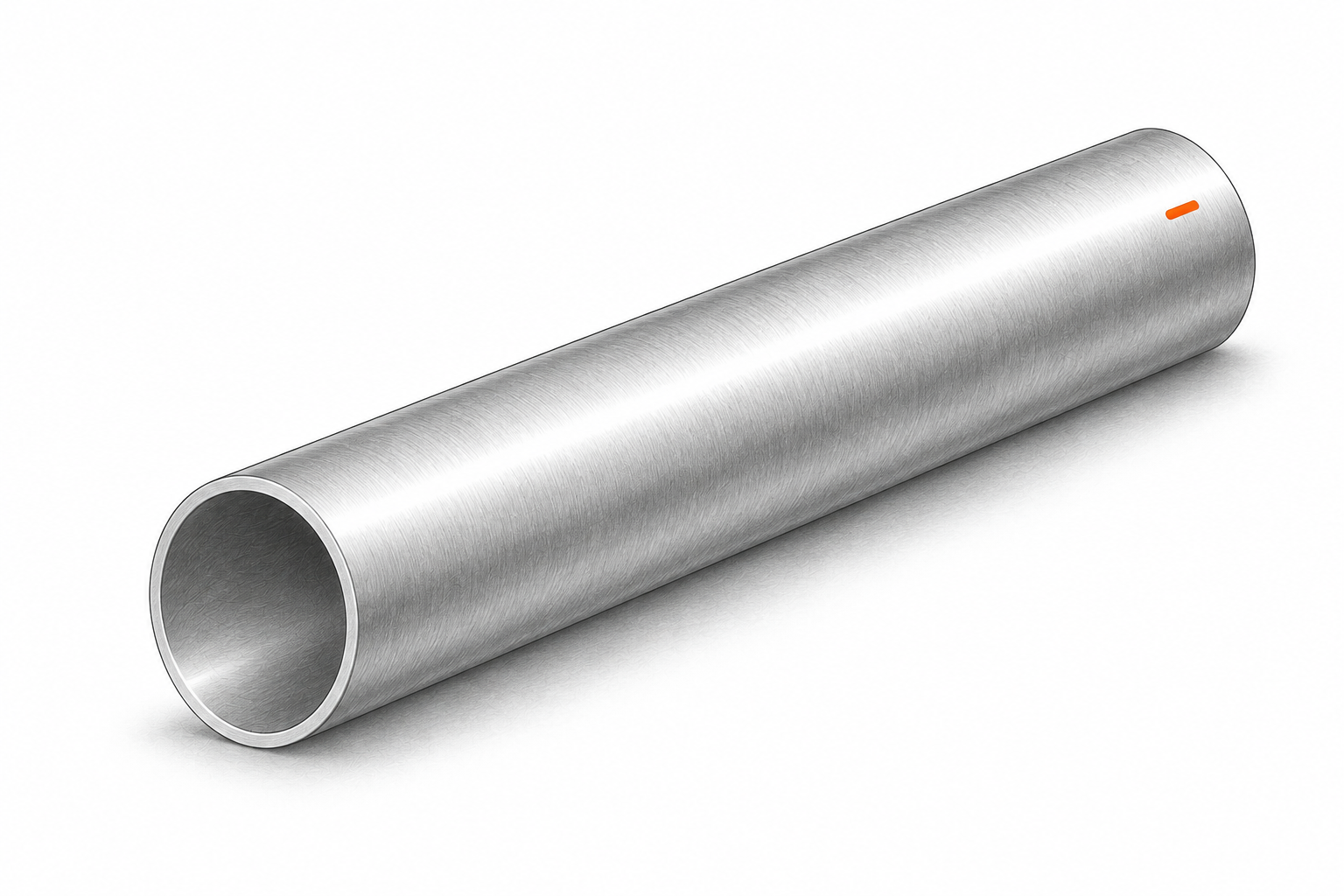
A smooth tube end is joined using the connection method specified for the equipment, commonly a brazed or soldered joint with the appropriate mating fitting. A smooth end alone does not identify its required size or joining procedure.
Male threaded connection
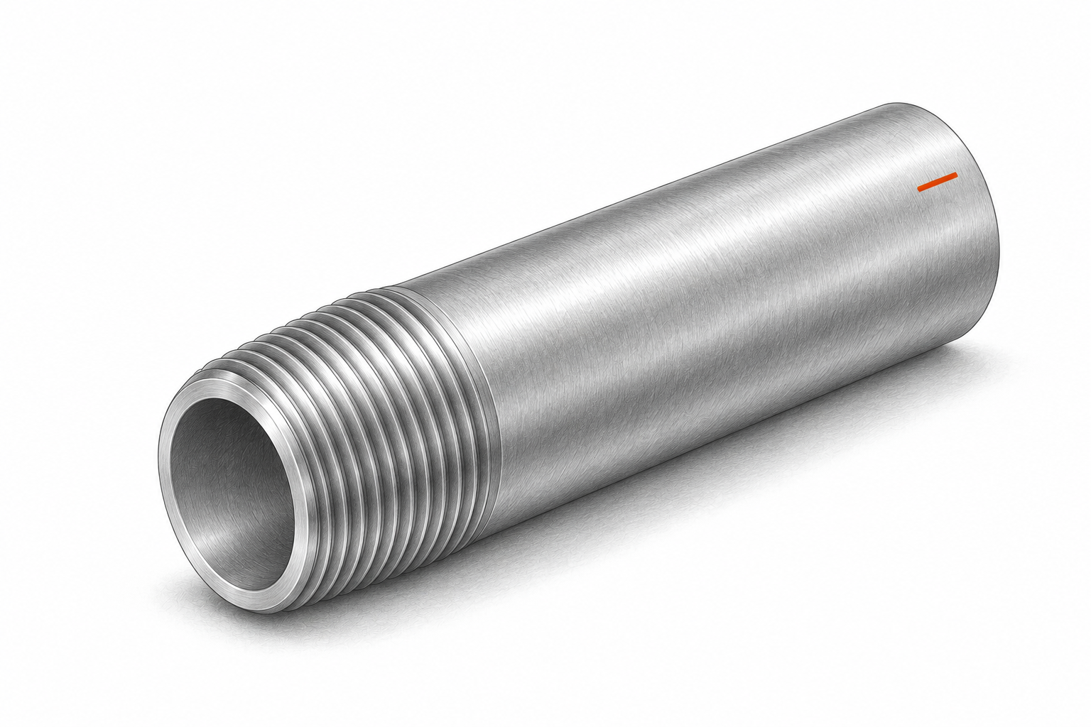
Male threads are on the outside of the connection and engage a compatible female fitting. Thread form and nominal size must match the system; a measured outside diameter is not the nominal pipe-size name.
Flanged connection
A flange joins to a compatible mating flange using the specified fasteners and sealing arrangement. Flange diameter, bolt pattern, face and rating are separate details; the pipe diameter alone does not describe the whole joint.
Connection handing
For the example below, view the coil from its air-entering face, looking in the airflow direction. Connections on your left are left-hand; connections on your right are right-hand. Confirm the convention on the actual drawing because a different viewpoint reverses what you see.
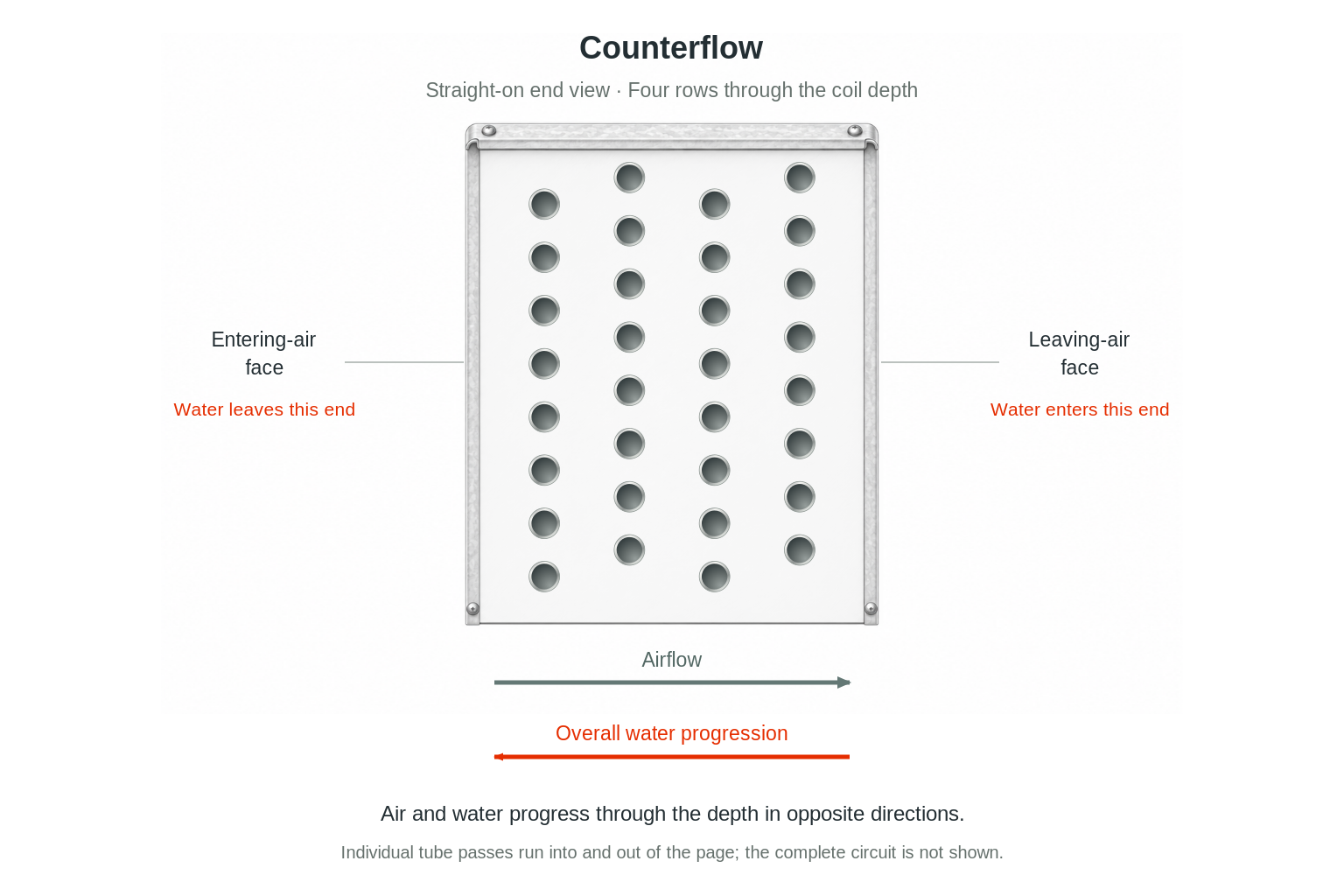
Airflow and fluid flow are separate directions
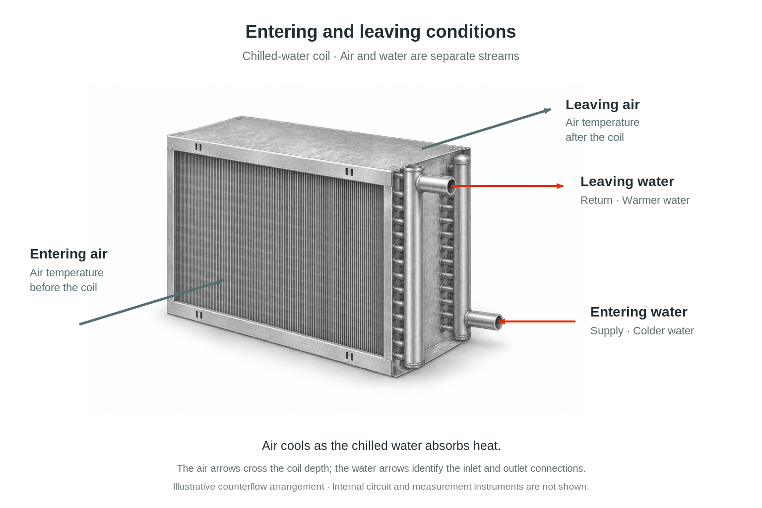
Air moves through the face and depth of the fin pack. Fluid follows the internal circuit. In an arrangement described as counterflow, the overall fluid progression opposes the air’s progression through the coil. The complete circuit can still contain many turns, so an external inlet location by itself does not prove the internal flow pattern.
Counterflow
In a counterflow arrangement, the overall fluid progression through the coil depth opposes the air’s progression. Individual tube passes still run across the face and may change direction many times. The drawing below identifies the overall progression, not a complete internal circuit.
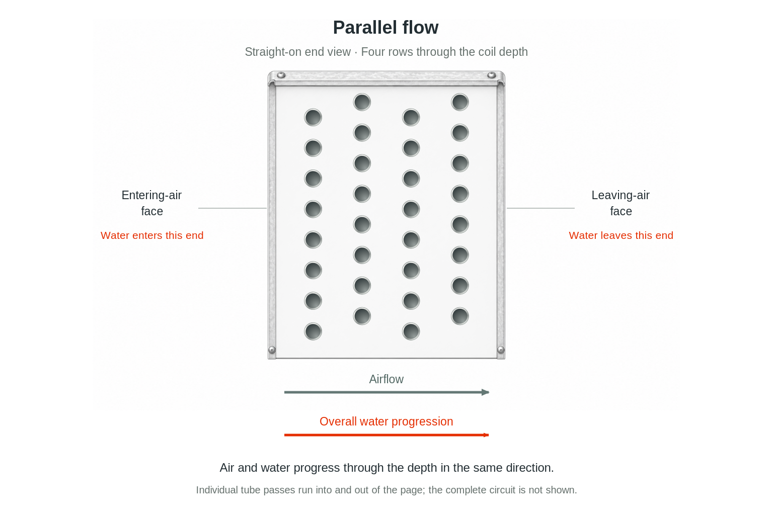
Parallel flow
In parallel flow, the two streams progress through the depth in the same overall direction. It is a different arrangement, not another word for parallel internal circuits. Use the specified circuit and piping arrangement for the actual coil.
07 / Materials and construction
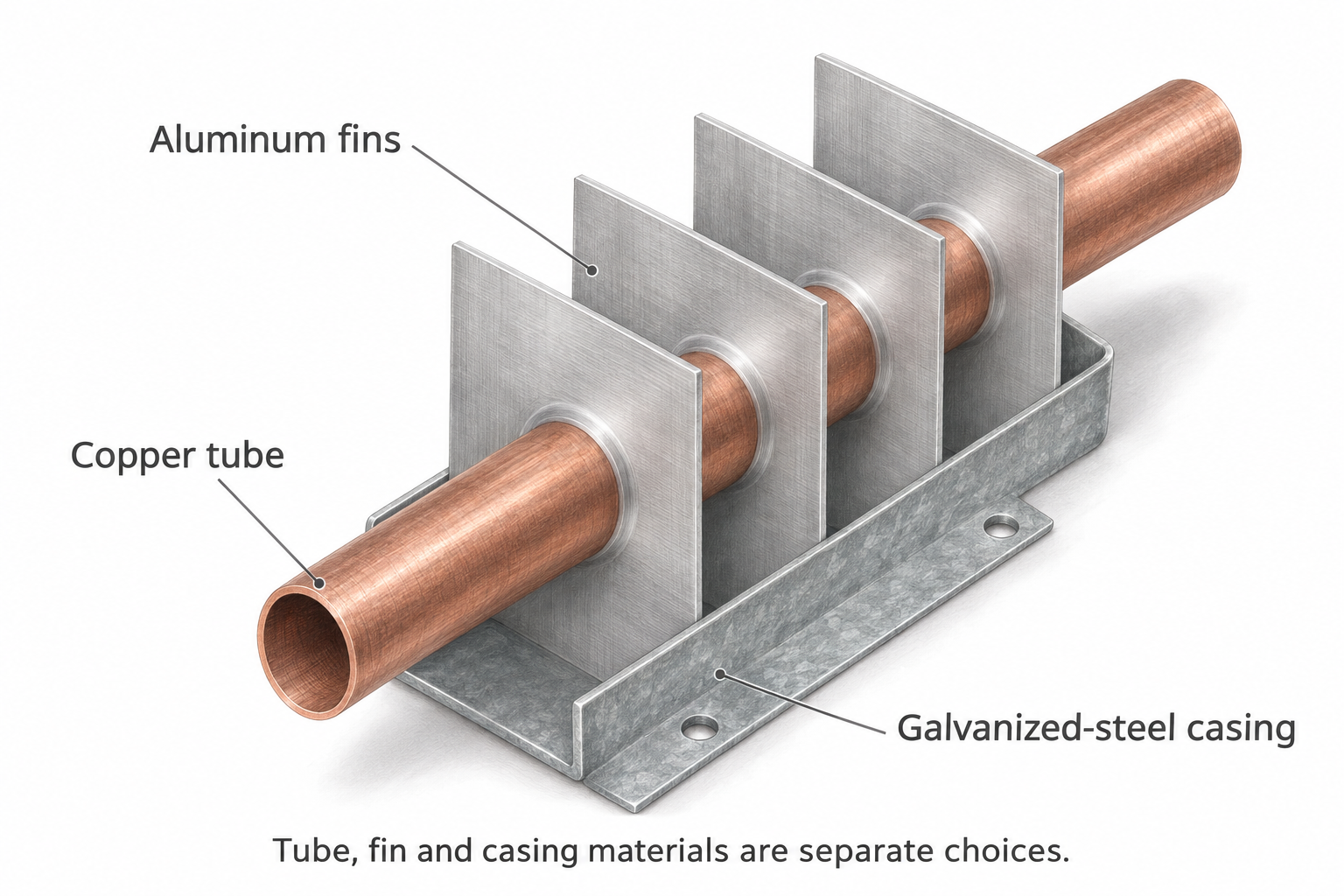
Tube, fin, and casing materials are separate choices
A conventional coil may combine copper tubes, aluminum fins, and a galvanized steel casing. Other materials are used where the fluid, environment, pressure, temperature, corrosion exposure, or equipment requirements call for them.
Describing a coil simply as “copper” is ambiguous. Identify the tubes, fins, casing, headers, and connections separately when those details matter. Their thicknesses and joining methods are also part of construction.
Coatings
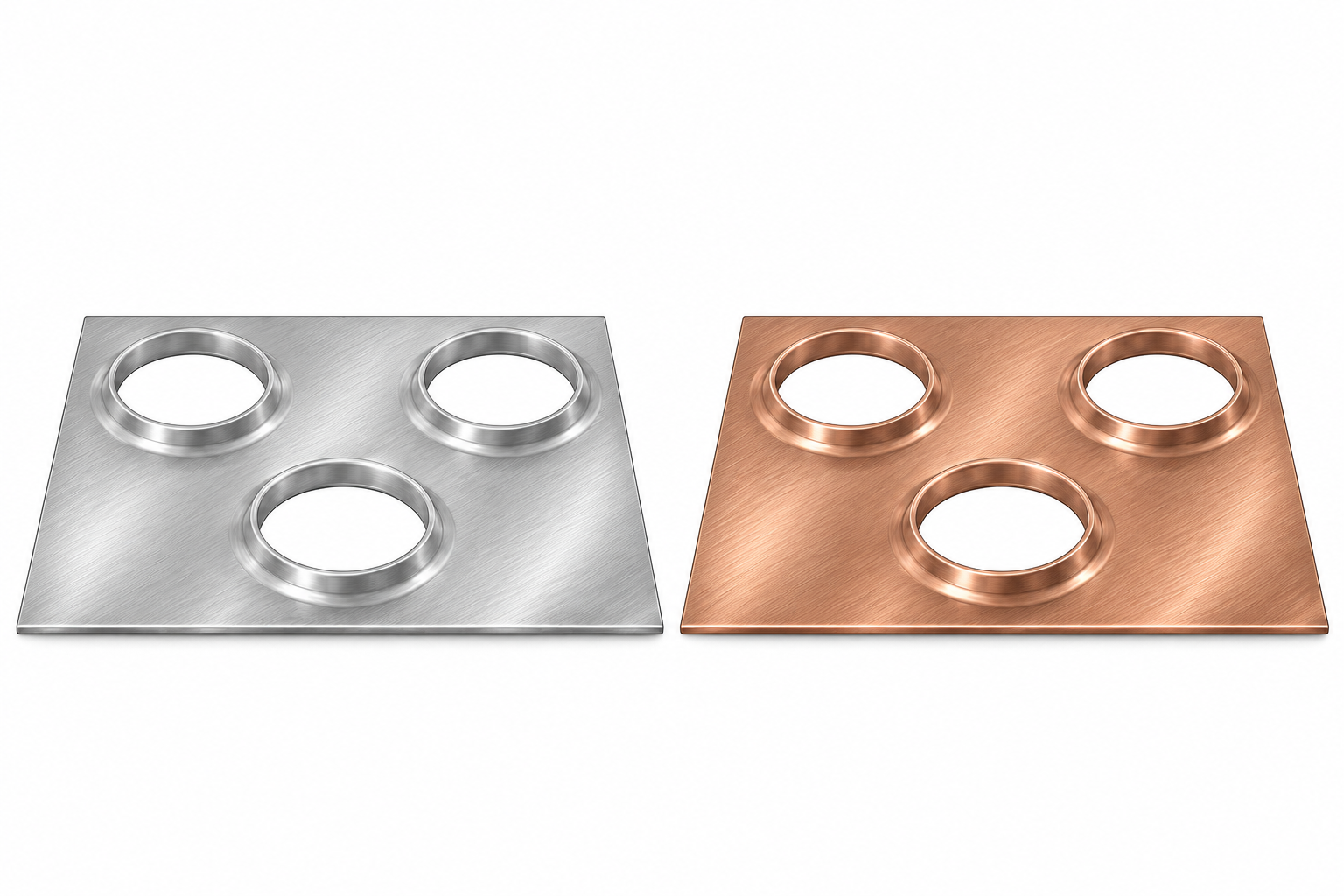
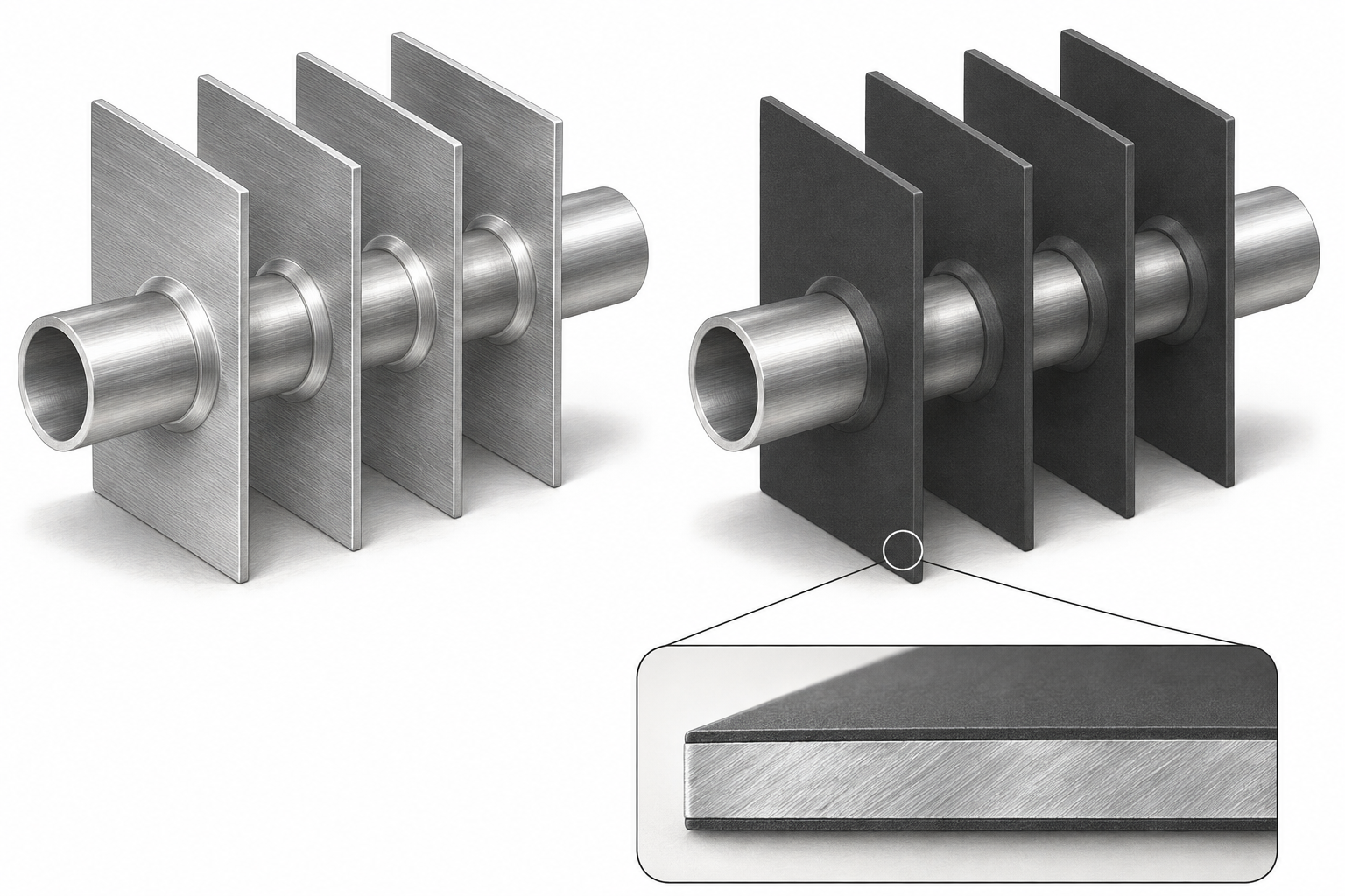
A coating is an added surface treatment that can help protect specified coil surfaces from the environment. Its suitability depends on the coating system and exposure. A coating is not a substitute for identifying the base materials or addressing dirt, drainage, and maintenance.
Round tube and plate fin versus microchannel
Conventional round tube and plate fin construction uses round tubes passing through thin fin plates. Many water, steam, evaporator, and condenser coils use this general construction family, with important differences inside.
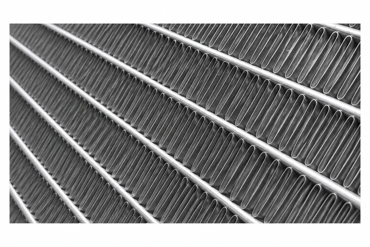
A microchannel coil typically uses flat tubes containing many small parallel passages, joined to headers with fins between the flat tubes. Many HVAC microchannel designs use aluminum construction. Microchannel describes how the heat exchanger is built; the system determines the duty it performs.
Neither construction label establishes interchangeability. Connection arrangements, working fluid, internal distribution, dimensions, and the equipment’s requirements still need to match.
Fins between flat tubes
Inside a multiport tube
08 / Basic performance terms
A coil’s dimensions describe its shape. Performance describes what it does under stated conditions. These terms help explain the difference.
Airflow and face velocity
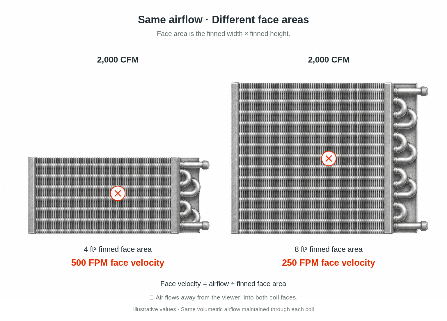
Airflow is the volume of air moving through the coil per unit time, commonly stated in cubic feet per minute, or CFM, or cubic meters per hour. Face velocity relates airflow to gross coil face area. It is not the same as the local speed through every small gap between fins.
For the same volumetric airflow, a larger finned face area gives a lower average face velocity. The example uses 2,000 CFM for both coils: 2,000 ÷ 4 ft² = 500 FPM, while 2,000 ÷ 8 ft² = 250 FPM. The airflow is held constant for the comparison; an actual fan and system may respond differently when resistance changes.
Entering and leaving conditions
Entering air temperature is the air temperature before the coil; leaving air temperature is after it. Entering and leaving fluid conditions describe the inside stream. Specify which stream a temperature belongs to.
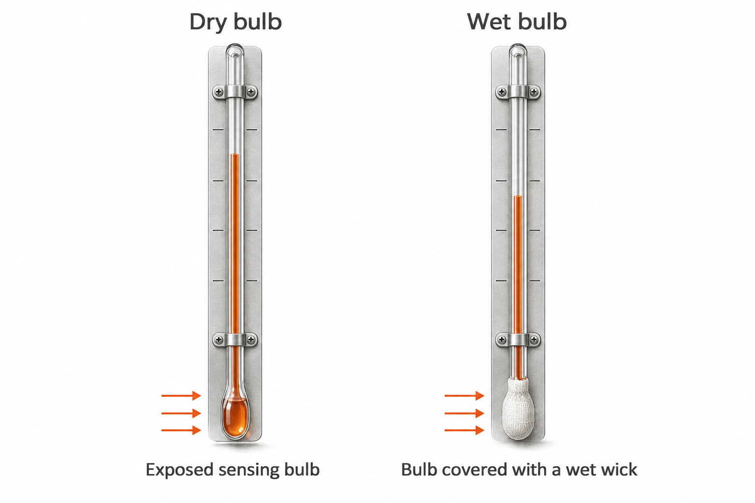
Dry-bulb temperature is the ordinary air temperature. Relative humidity describes how close the air is to saturation at its current temperature. Wet-bulb temperature is another air-condition measurement used with dry bulb to describe moisture and energy conditions.
A wet-bulb measurement uses a wetted wick and adequate airflow. Evaporation cools the wetted bulb; in unsaturated air, its reading is lower than the dry-bulb reading. At saturation, the readings converge. Wet bulb is not the temperature of collected condensate. Modern instruments may calculate wet-bulb temperature from other measured air properties.
Relative humidity
Relative humidity, or RH, compares the air’s water-vapor pressure with the saturation vapor pressure at that air temperature. It is expressed as a percentage. RH can change when temperature changes even if no water vapor is added or removed, so a relative-humidity reading should be paired with an air temperature.
Dew point and condensation
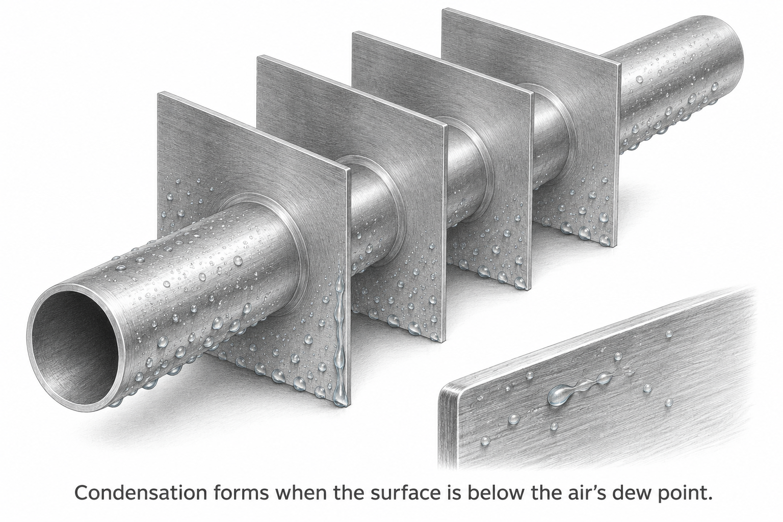
The dew point is the temperature at which air at its current moisture content reaches saturation when cooled at approximately constant pressure. When a coil surface is colder than the air’s dew point, water can form on that surface.
That moisture is air-side condensate. It differs from steam-side condensate formed inside a steam coil. A cooling coil can cool air without collecting water when its surface does not reach the conditions needed for condensation.
Capacity, sensible heat, and latent heat
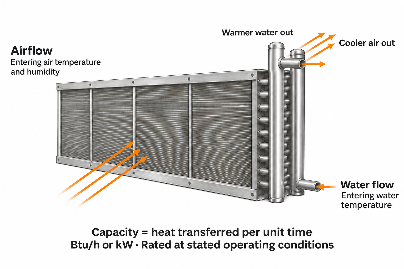
Capacity is a rate of heat transfer, commonly expressed in Btu/h or kW. It is tied to specified air and fluid conditions, not simply to a coil’s size.
Sensible cooling lowers air temperature. Latent cooling removes moisture by condensation. Total cooling capacity includes both contributions when both occur. Two selections with the same total capacity can remove different amounts of moisture.
A ton of refrigeration is another capacity unit: 12,000 Btu/h, approximately 3.52 kW of heat transfer. Capacity in kW is thermal output, not automatically the electrical power consumed by the whole system. A larger temperature difference or flow rate does not guarantee proportionally more capacity; both streams and the coil construction impose limits.
Sensible and latent cooling
Flow rate and pressure drop
Fluid flow rate describes how much working fluid passes through the coil per unit time. Liquid flow is often stated in gallons per minute or liters per second; steam and refrigerant flow may be stated by mass.
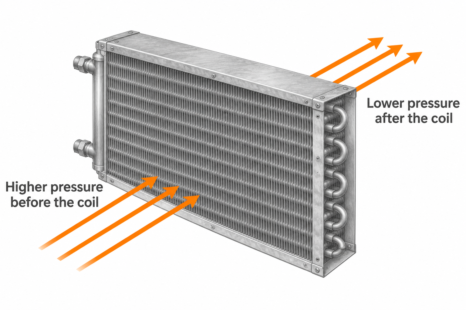
Pressure drop is the loss of pressure as a stream passes through a component. Air-side pressure drop relates to the fan’s task; fluid-side pressure drop relates to the circulating or refrigeration system. They are different values with different units and reference conditions.
Air-side pressure drop
Water-side pressure drop
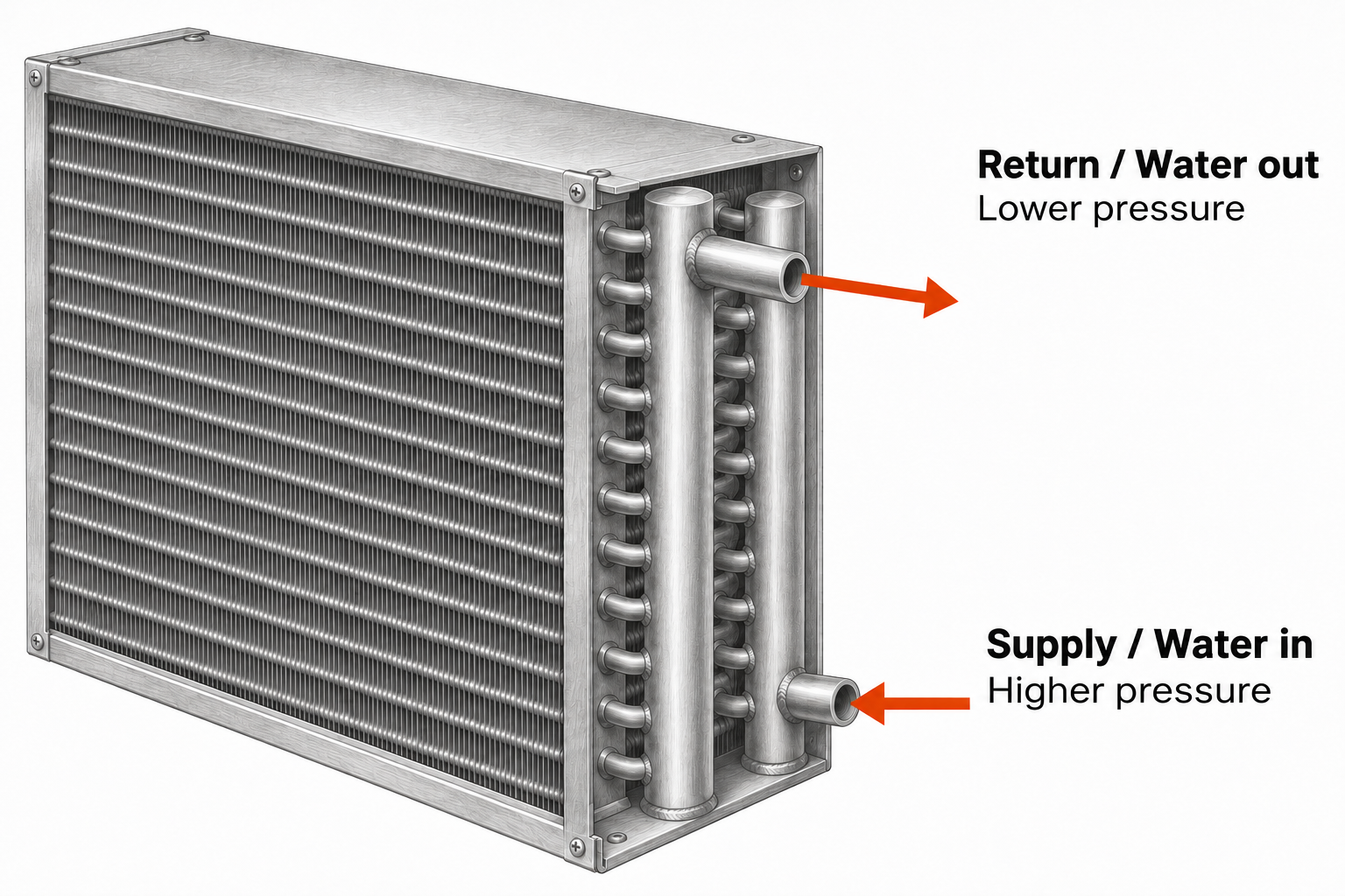
Operating pressure is the pressure during operation. A design pressure or specified pressure rating concerns the component’s intended pressure suitability. Neither is the same as pressure drop, and a pressure rating does not describe heating or cooling capacity.
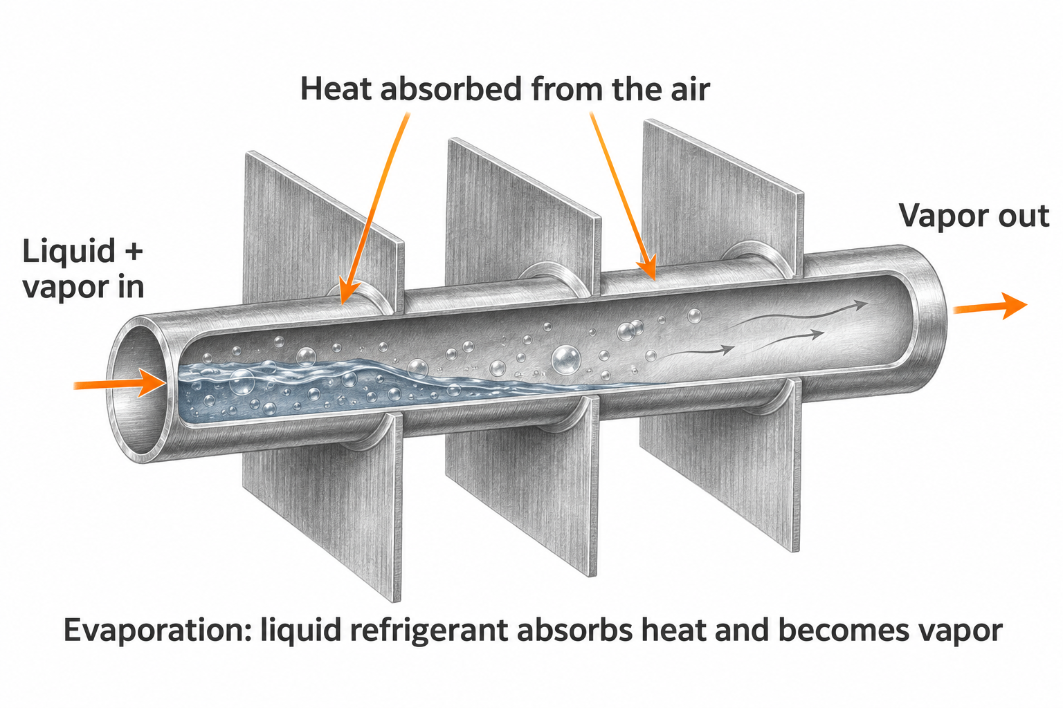
Evaporation inside a DX coil
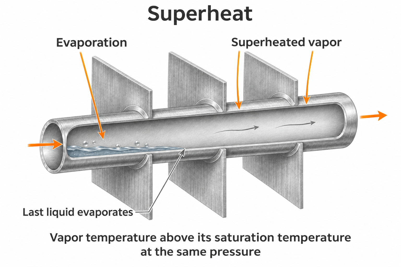
Evaporation is the change from liquid to vapor as refrigerant absorbs heat. A typical DX coil receives a liquid–vapor mixture downstream of the expansion device; the remaining liquid evaporates inside the coil. The refrigerant and the air remain separated by metal.
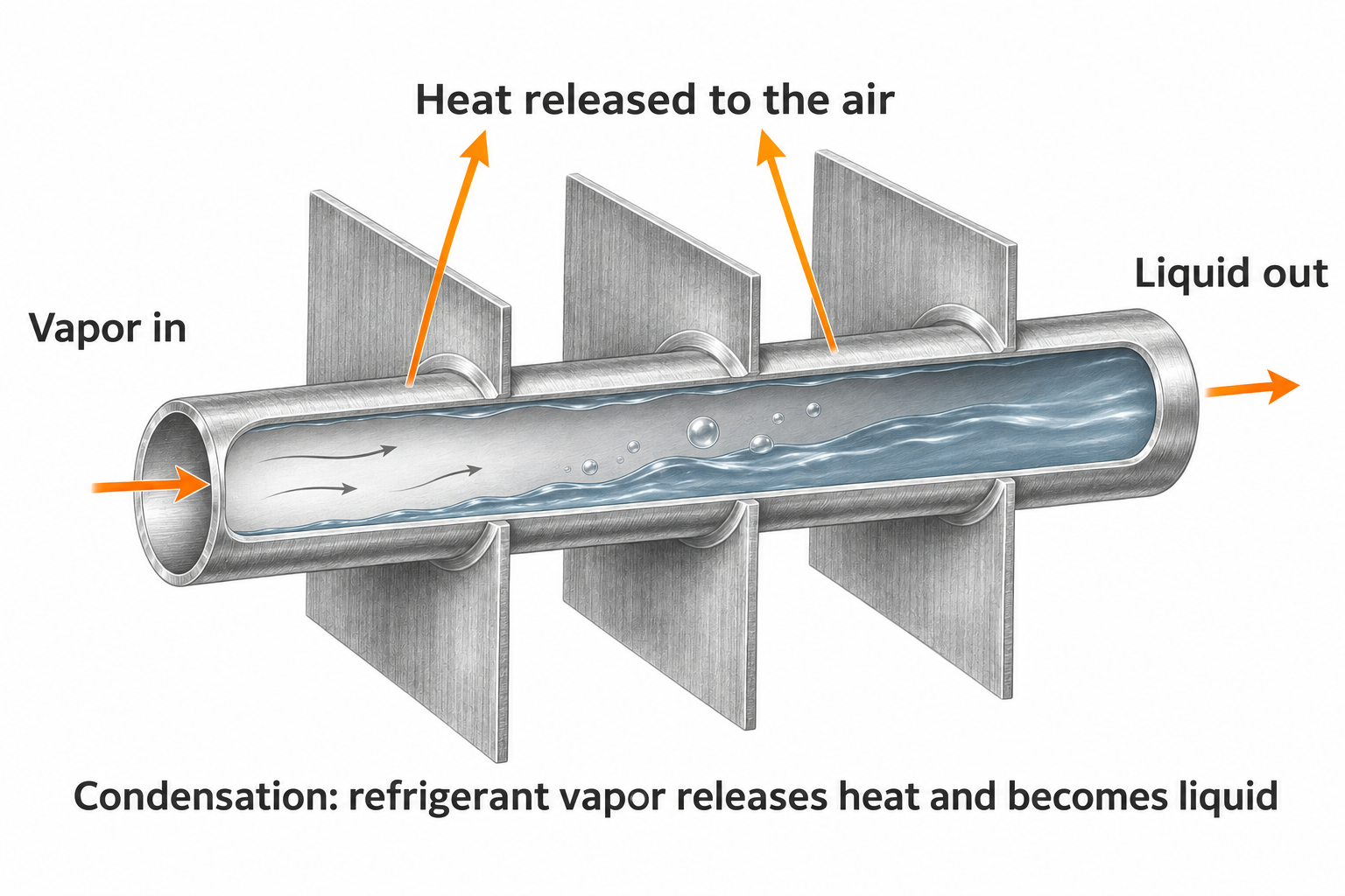
Condensation inside a condenser
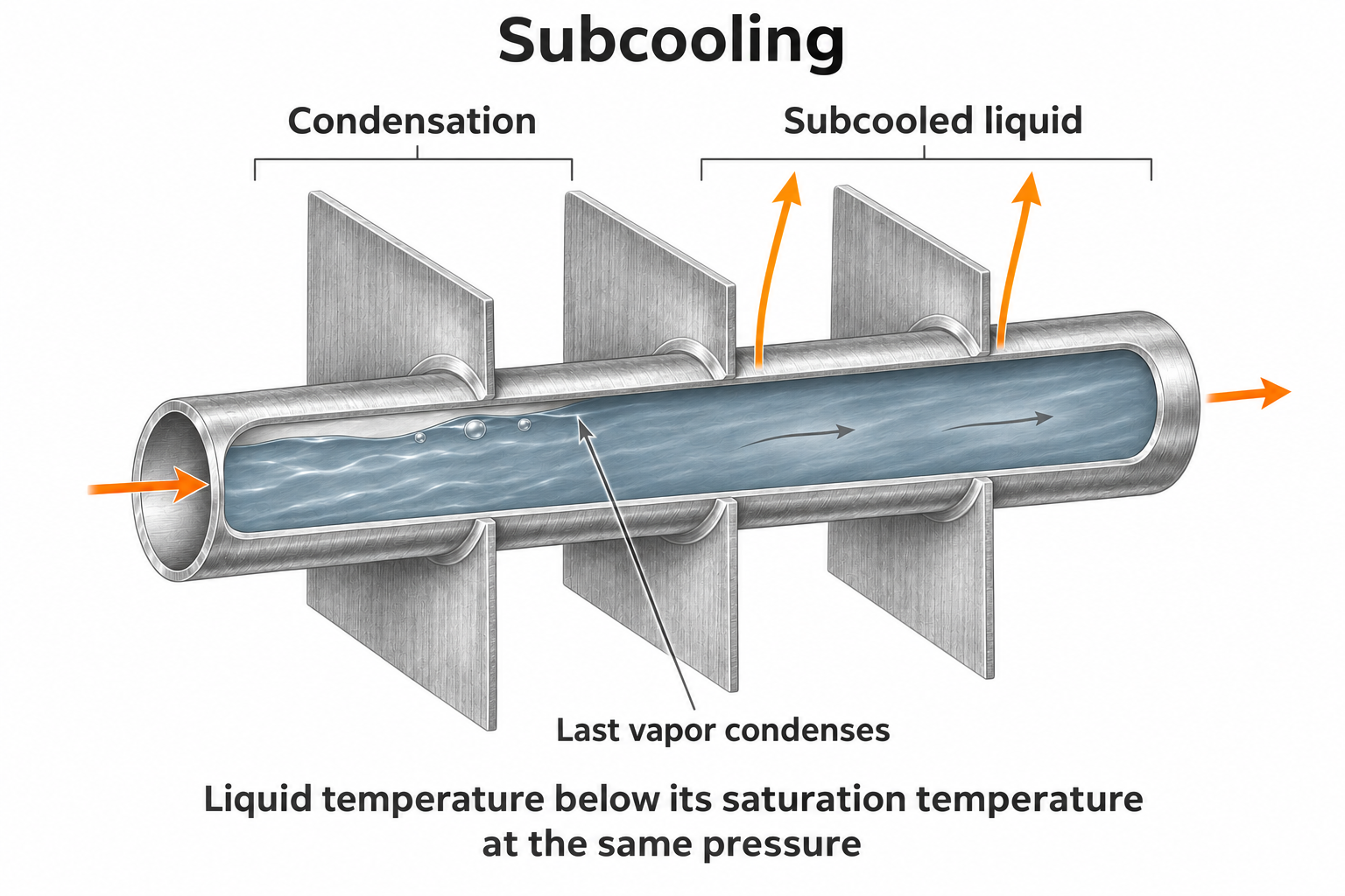
Condensation is the reverse phase change: refrigerant vapor gives up heat and becomes liquid. In a conventional condenser, incoming superheated vapor first cools toward saturation, then condenses. The liquid can then cool further. This is refrigerant condensation inside the tube, not moisture collecting outside a chilled-water coil.
Superheat and subcooling
For refrigerant coils, superheat describes how far vapor temperature is above the appropriate saturation temperature at the stated pressure. Subcooling describes how far liquid temperature is below its appropriate saturation temperature. These are refrigerant condition terms, not descriptions of how hot or cold the passing air feels.
A saturation temperature is tied to refrigerant pressure. Superheat and subcooling therefore require a temperature and the appropriate pressure-based saturation reference; temperature alone is not enough. For refrigerant blends with temperature glide, use the applicable dew-point reference for vapor superheat and bubble-point reference for liquid subcooling.
Superheat
Subcooling
09 / Common misunderstandings, cleared up
“All cooling coils use refrigerant.”
Chilled water coils cool air with a circulating liquid. DX evaporator coils cool air using refrigerant that evaporates inside the coil. Their shared job does not make their internal requirements the same.
“Rows are the tubes I can count from bottom to top.”
Rows run through the depth in the airflow direction. Tubes stacked vertically describe another direction. Fin spacing describes a third feature: how closely the fins are packed along the tubes.
“The same outside dimensions mean the same coil.”
Matching the envelope can help physical fit, but it does not confirm internal circuiting, materials, working-fluid suitability, pressure rating, capacity, or connection details.
“A larger or denser coil must work better.”
More rows or fins can change several characteristics at once. Available airflow, fan pressure, fluid conditions, cleaning access, and the required duty determine whether that change is useful.
“Water on a coil means it is leaking.”
A cooling coil can normally collect water from the air. A steam coil normally produces condensate inside its tubes. A leak is a separate condition that needs to be distinguished from those expected processes.
“A coil type tells me everything I need.”
The type identifies part of the story. A useful description combines its job, working fluid, construction, physical fit, and operating conditions. That is what turns a familiar-looking metal assembly into a coil you can meaningfully identify.
Use the words in this article as a checklist for reading a drawing: identify the duty and fluid, define the air faces, name the components, distinguish face dimensions from casing dimensions, separate rows from tubes high, and keep thermal performance separate from pressure ratings.
Coil Recall
Review the article’s main ideas, one card at a time.
Card 1 of 7